5-31
Cisco 7600 Series Router Installation Guide
OL-4503-24
Chapter 5 Removal and Replacement Procedures
Removing and Replacing the Power Supply
Note The 6000 W DC-input power supply provides voltages of 2800 W, 4500 W, or 6000 W for single and
redundant configurations. Some configurations require cable tie-wraps, depending on available DC input
pairs. For more information, refer to Installing a PWR-6000-DC Power Supply in a Cisco 7609 or a
Cisco 7609-S Router, page 5-74.
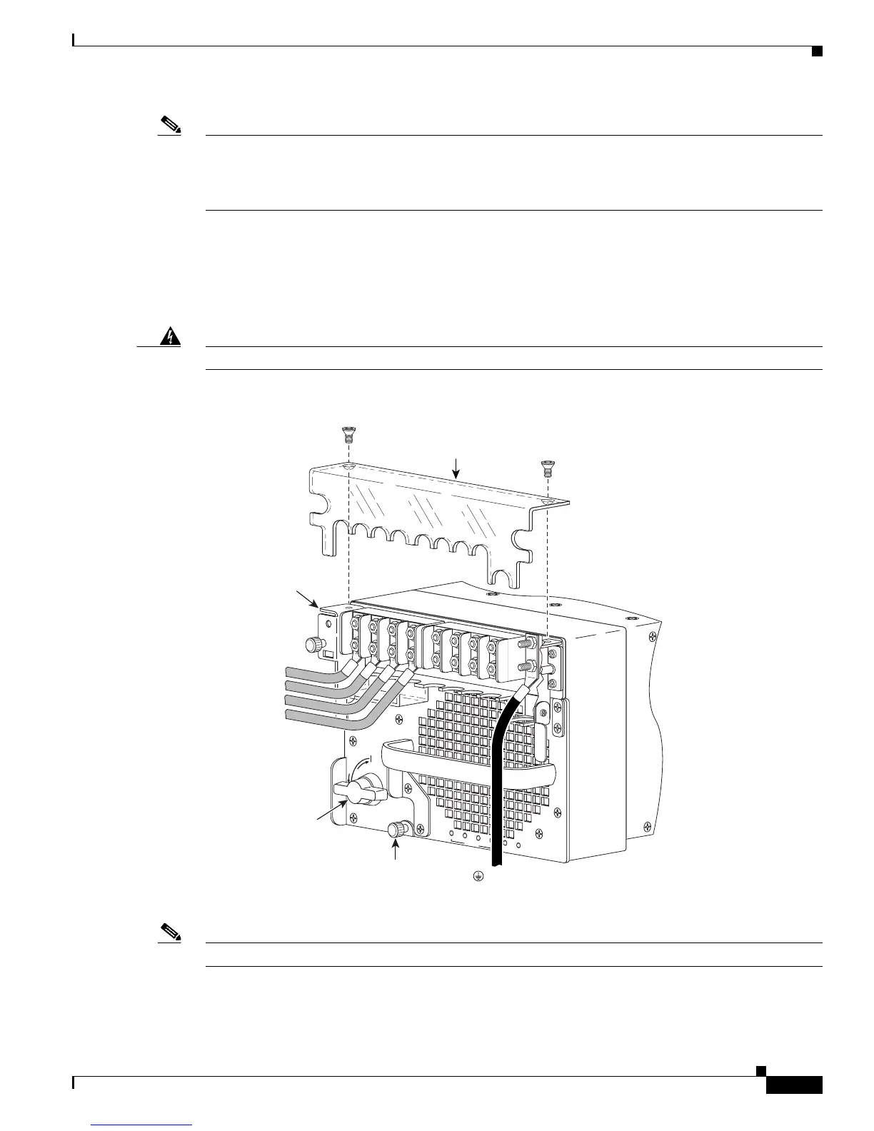
Step 5 Disconnect the DC-input wires from the terminal block in this order:
• Positive (+)
• Negative (-)
Step 6 Disconnect the PWR-6000-DC power supply ground.
Warning
When installing the unit, the ground connection must always be made first and disconnected last.
Figure 5-34 DC-Input Wire Connections for 6000-W DC-Input Power Supply (2800W DC-input shown)
Note If you are not going to remove the IPM, skip steps 7 and 8 and go to step 9.
Step 7 Loosen the IPM captive installation screws on the power supply. See Figure 5-33.
Step 8 Lift up on both IPM latches and remove the IPM. See Figure 5-35.
191287
R
U
N
I
N
S
T
A
L
L
CISCO SYSTEMS, INC
1
2
3
4
INPUT OK
FAN
OK
OUTPUT
FAI L
Captive
installation
screw
Terminal
block cover
( - ) Negative
(+) Positive
( - ) Negative
(+) Positive
Power leads
attached to
terminal block
( ) Ground
Input power
module
Power
switch



 To Next Page