5-36
Cisco 7600 Series Router Installation Guide
OL-4503-24
Chapter 5 Removal and Replacement Procedures
Removing and Replacing the Power Supply
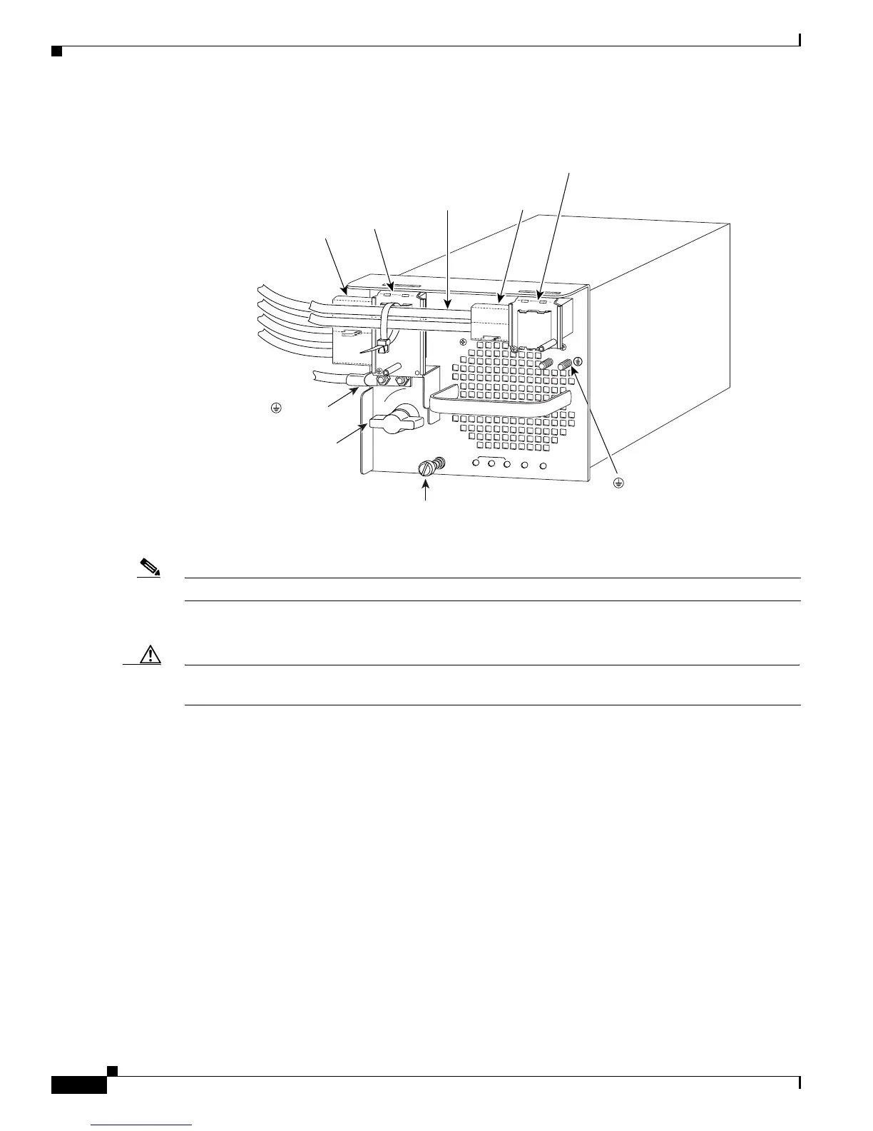
Figure 5-39 DC-Input Wire Connections for 4000-W DC-Input Power Supply
Note Figure 5-39 shows a 4000 W configuration that requires cable tie-wraps.
Step 9 Loosen the captive installation screw on the power supply (Figure 5-39).
Caution Use both hands to install and remove power supplies. Each DC-input power supply weighs between 22
pounds (9.9 kg) and 33 pounds (15 kg).
Step 10 Grasp the power supply handle with one hand and slide the power supply part of the way out of the
chassis. Place your other hand underneath the power supply, as shown in Figure 5-40, and slide the
power supply completely out of the chassis.
114008
3
INPUT OK
FAN
OK
OUTPUT
FAIL
I
0
1
2
Captive
installation
screw
( ) Ground
(+) Positive
( - ) Negative
Power
switch
( ) Ground
(+) Positive
( - ) Negative
Power leads
attached to
terminal block
Terminal
block cover
Plastic
insulator
Power leads
attached to
terminal block
(+) Positive
( - ) Negative
Terminal
block cover
Plastic
insulator



 To Next Page