5-48
Cisco 7600 Series Router Installation Guide
OL-4503-24
Chapter 5 Removal and Replacement Procedures
Removing and Replacing the Power Supply
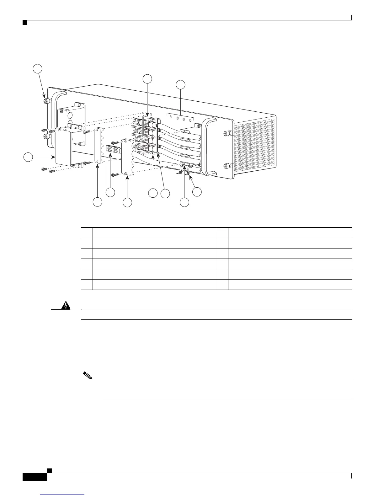
Figure 5-52 DC-Input Front Panel for 2700-W DC-Input Power Supply
Warning
Power supply captive installation screws must be tight to ensure protective grounding continuity.
Step 5 Remove the four screws securing the terminal block cover, and slide the cover off of the terminal block
(Figure 5-52).
Step 6 Attach the appropriate lugs to the DC-input wires and ground wire. The wires should be sized according
to local and national installation requirements. Use only copper wire. The maximum width of a lug is
0.600 inch (15.2 mm).
Note For 2700 W power supplies, use fine-stranded copper conductors rated for 90-degrees Celsius
for North American installations.
1 Captive installation screw 7 Cable holder cover
2 DC power cable terminal block 8 Cable holder
3 Status LEDs 9 Tie-wrap
4 DC power cable terminal block cover 10 Cable holder
5 Cable holder cover 11 Tie-wrap
6 Ground
132219
PWR-2700-DC/4
-VE-1
-VE-1
-VE-2
-VE-2
IN
P
U
T1
O
K
4
8V-60V
=40A
IN
P
U
T2
O
K
48V
-60
V
=4
0A
FA
N
O
K
O
U
T
PU
T
FA
I
L
ALL FASTENERS M
UST BE F
ULL
Y ENGAGED
PRIOR TO OPERA
TING THE PO
W
ER SUPPLY
3
2
6
4
10
1
8
5
7
11
9



 To Next Page