5-5
Cisco 7600 Series Router Installation Guide
OL-4503-24
Chapter 5 Removal and Replacement Procedures
Removing and Replacing the Power Supply
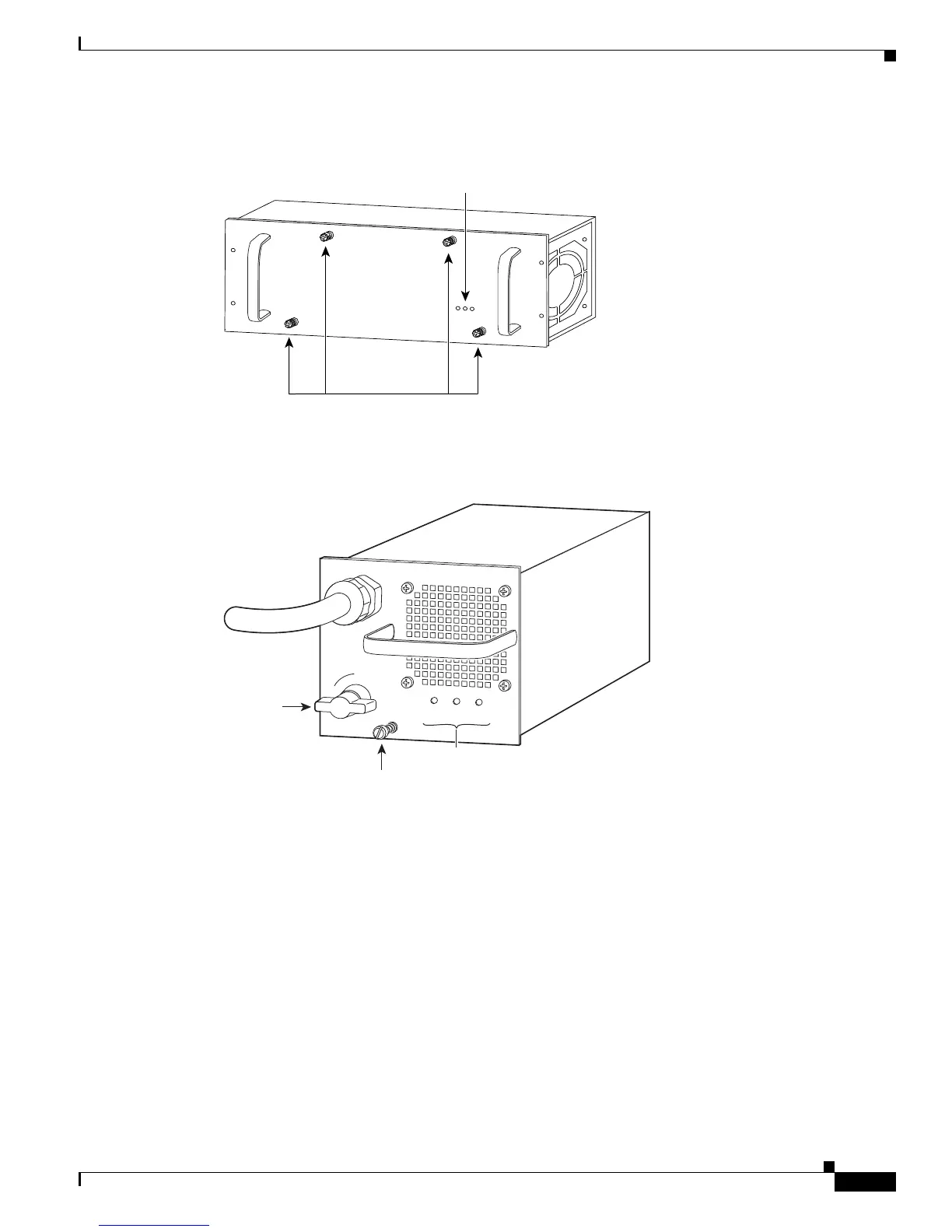
Figure 5-3 Cisco 7604 Router , Cisco 7606 Router, Cisco 7606-S—Power Supply Captive Installation
Screws
Figure 5-4 Cisco 7609 Router, Cisco 7609-S Router, and Cisco 7613 Router— Power Supply Captive
Installation Screws
Step 5 Cisco 7603 router, Cisco 7609 router, Cisco 7609-S, and Cisco 7613 router—Grasp the power supply
handle with one hand and slide the power supply part of the way out of the chassis. Place your other hand
underneath the power supply (see Figure 5-5 for Cisco 7603 router, and Figure 5-6 for Cisco 7609, Cisco
609-S, and Cisco 7613 routers), and slide the power supply completely out of the chassis.
Cisco 7604, Cisco 7606 router, Cisco 7606-S router—Grasp both power supply handles, as shown in
Figure 5-7, and slide the power supply completely out of the chassis.
INPUT OK
FAN OK
OUTPUT FAIL
63895
Captive installation screws
Status LEDs
Power
switch
INPUT
OK
FAN
OK
OUTPU
T
FAIL
Captive installation
screw
Status LEDs
85756
I
0