5-50
Cisco 7600 Series Router Installation Guide
OL-4503-24
Chapter 5 Removal and Replacement Procedures
Removing and Replacing the Power Supply
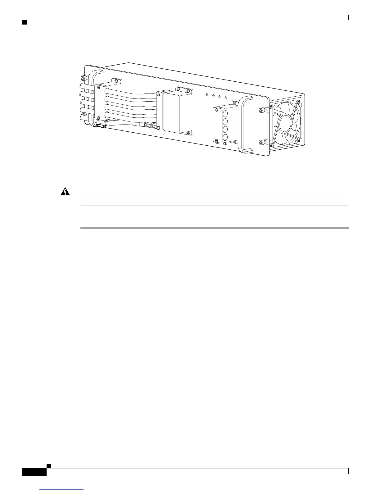
Figure 5-53 DC-Input Wires on Left Side
Installing a PWR-1900-DC Power Supply in a Cisco 7606 Router
Warning
Before performing any of the following procedures, ensure that power is removed from the DC circuit.
Follow these steps to install a DC-input power supply:
Step 1 Ensure that the system (earth) ground connection has been made. For ground connection installation
instructions, see the “System Ground Connection” section on page 3-19.
Step 2 Verify that power is off to the DC circuit connected to the DC PEM for the power supply you are
installing.
Grasp both power supply handles, as shown in Figure 5-54. Slide the power supply into the power supply
bay. Make sure that the power supply is fully seated in the bay.
132220
IN
PU
T1
O
K
48V-60V
=40A
INP
U
T2
O
K
48
V-60
V
=4
0A
FA
N
O
K
O
U
TPU
T
FA
IL
ALL FASTENERS MUST BE FULLY ENG
AGED
PRIOR TO OPERATING THE POW
ER SUPPLY
PWR-2700-DC/4



 To Next Page