EasyManua.ls Logo

Cisco Aironet AIR-PWRINJ6 - User Manual

Cisco Aironet AIR-PWRINJ6
7 pages
Print Icon
To Next Page IconTo Next Page
Loading...
12/9/2019 Cisco Aironet Power Injector AIR-PWRINJ6= Installation Guide - Cisco
https://www.cisco.com/c/en/us/td/docs/wireless/access_point/power/guide/air_pwrinj6.html 1/7
Cisco Aironet Power Injector AIR-PWRINJ6= Installation GuideAIR-PWRINJ6=
Table of Contents
Cisco Aironet Power Injector AIR-PWRINJ6= GuideAIR-PWRINJ6=
Product Overview
Unpacking the Power Injector
Additional Requirements
Disable PoE on the Connected Switchport
Installing the Power Injector
Mounting Instructions
Using the Mounting Tabs
Specications
Regulatory Information
Cisco Aironet Power Injector AIR-PWRINJ6= GuideAIR-PWRINJ6=
This document describes the Cisco Aironet series access point power injector AIR-PWRINJ6= (referred to asAIR-PWRINJ6=
the power injector in this document) and provides instructions for mounting them.
Product Overview
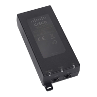
The Cisco Aironet Power Injector AIR-PWRINJ6= increases wireless LAN deployment exibility of supportedAIR-PWRINJ6=
Cisco Aironet Access Points by providing an alternative powering option to local power, inline power-capable
multiport switches, and multiport power patch panels.
The single-port PoE injector provides up to 30 Watts and is compliant with IEEE 802.3af (15.4 W) and IEEE
802.3at (30 W) systems. This power injector is for use with the Cisco Aironet 2800 series and 3800 series
access points.
Note The Cisco Aironet Power Injector AIR-PWRINJ6= is not weatherproof and hence is not meant to beAIR-PWRINJ6=
used outdoors.
A Category 5 or better Ethernet cable connects the injector to a 10/100/1000 Ethernet switch, hub, or
network, and another cable carries power and data to the access point's WAN Ethernet port. The power
injector’s built-in power supply has a C13 connector that connects to a wall outlet or power strip. The power
injector connects to a wall outlet or power strip.
Caution To avoid overheating and possible failure, do not stack or tie together (bundle) the power injector
and its AC power cable.
Question and Answer IconNeed help?

Do you have a question about the Cisco Aironet AIR-PWRINJ6 and is the answer not in the manual?

Summary

Product Overview

Unpacking the Power Injector

Additional Requirements

Disable PoE on the Connected Switchport

Installing the Power Injector

Mounting Instructions

Guidance on how to mount the power injector to vertical or horizontal surfaces using its mounting tabs.

Using the Mounting Tabs

Lists tools and steps required to mount the power injector using its mounting tabs and screws.

Specifications

Regulatory Information

Overview

The Cisco Aironet Power Injector AIR-PWRINJ6= is a single-port Power over Ethernet (PoE) injector designed to enhance the deployment flexibility of supported Cisco Aironet Access Points. It provides an alternative power option to local power, inline power-capable multiport switches, and multiport power patch panels, making it suitable for various wireless LAN installations.

Function Description:

The AIR-PWRINJ6= acts as an intermediary device, connecting an Ethernet switch, hub, or network to a Cisco Aironet Access Point. It injects power into the Ethernet cable, allowing the access point to receive both data and power over a single cable, simplifying installation and reducing cabling requirements. This injector is specifically designed for use with the Cisco Aironet 2800 series and 3800 series access points. It supports up to 30 Watts of power and is compliant with both IEEE 802.3af (15.4 W) and IEEE 802.3at (30 W) PoE standards. The injector features an "AP Connector Port (Data + Power Out)" for connection to the access point and a "Switch Connector Port (Data In)" for connection to the network switch. It also has a C13 power connector for its built-in power supply, which connects to a wall outlet or power strip.

Important Technical Specifications:

  • Models: Two models exist, functionally identical but with minor cosmetic differences.
  • Dimensions (W, H, L):
    • Model 1: 53 mm x 32.5 mm x 140 mm (2.09 in x 1.28 in x 5.5 in)
    • Model 2: 65 mm x 36 mm x 140 mm (2.55 in x 1.42 in x 5.51 in)
  • Data Rates: 10/100/1000 Mbps
  • PoE Output:
    • Pin Assignment and Polarity: 4/5 (+), 7/8 (-)
    • Output Power Voltage: 55V DC
  • User Port Power: 30 Watts
  • Input Power Requirements:
    • AC Input Voltage: 100 to 240V AC
    • AC Input Current: 0.67 A @ 100 - 240 V AC
    • AC Frequency: 50 to 60 Hz
  • Weight:
    • Model 1: 0.44 lbs (200 g)
    • Model 2: 0.47 lbs (215 g)
  • Connectors: Shielded RJ-45, EIA 568A and 568B
  • Environmental Conditions:
    • Operating Ambient Temperature: -4°F to 104°F (-20°C to 40°C) at 30 W; -4°F to 122°F (-20°C to 50°C) at 25 W
    • Operating Humidity: Maximum 90%, Non-condensing
    • Storage Temperature: -4°F to 158°F (-20°C to 70°C)
  • Reliability: MTBF: 100,000 hrs @ 25°C
  • Thermal Rating: 20 BTU/Hr @ 240 V AC
  • Regulatory Compliance: IEEE 802.3at (PoE), China RoHS Compliant, WEEE Compliant, CE Compliant, FCC Part 15 Class B, EN 55022 Class B (Emissions), EN 55024 (Immunity), VCCI, UL 60950-1, IEC/EN 60950-1.

Usage Features:

  • Installation: The installation process involves plugging a Category-5 Ethernet cable from the injector's "AP" port to the access point's WAN uplink Ethernet port, and another Category-5 Ethernet cable from the injector's "Switch" port to the 10/100/1000 Ethernet switch, hub, or network. The power injector's C13 connector then connects to a wall outlet or power strip.
  • Status LED: A Status LED provides visual feedback on the injector's operational status.
    • AC Power: Depending on the model, the LED is amber or blinks green to indicate that the Power Injector is powered ON and ready for connection.
    • AP Power: The LED lights solid green to indicate that a valid IEEE 802.3af or 802.3at load (AP) is detected and powered ON. The LED remains green when powering the Access Point, even if the uplink is not connected, signifying that the power injector is providing power to the Access Point.
  • Mounting: The power injector can be mounted to vertical or horizontal surfaces using integrated mounting tabs located on the top right and bottom left of the unit. Mounting requires two #6 plastic wall anchors (for drywall), two #6 x 1-in. (2.5 cm) sheet-metal screws, a drill with a 3/16-in (0.48-cm) drill bit, a Phillips head screwdriver, and a small hammer. The mounting process involves marking hole locations using the tabs as a template, drilling holes, installing anchors (if applicable), aligning the injector, inserting screws, and driving them into the surface.
  • Cable Length: The maximum supported distance for in-line power is 328 ft. (100 m), which includes the length of the 6.5-ft. (2-m) Ethernet cable provided with the power injector.
  • PoE Disablement: In scenarios where the access point is connected to the AIR-PWRINJ6=, which is then cabled to an 802.3af PoE-enabled switchport, it may be necessary to disable PoE on the switchport. Failure to do so can prevent the injector from supplying full power to the AP, potentially leading to issues like disabled radios due to intermittent reception of only 15.4W of power. PoE can be disabled on the connected switchport by executing the power inline never command at the CLI prompt of the Cisco switch in interface config mode.

Maintenance Features:

  • Overheating Prevention: To avoid overheating and potential failure, it is crucial not to stack or tie together (bundle) the power injector and its AC power cable.
  • Environmental Considerations: The AIR-PWRINJ6= is not weatherproof and is explicitly not meant for outdoor use. It should also not be installed in plenum airspaces. When installing the access point in environmental air spaces (e.g., above a suspended ceiling), ensure that the Ethernet cable meets national and local safety codes.
  • Troubleshooting Interference: If the equipment causes interference with radio or television reception, troubleshooting steps include turning the equipment off to isolate the source, reorienting the television or radio antenna, moving the equipment farther away from the television or radio, or plugging the equipment into an outlet on a different circuit from the television or radio.
  • Unauthorized Modifications: Any modifications to the product not authorized by Cisco Systems, Inc. will void the FCC approval and the user's authority to operate the product.
  • Package Contents: The typical package includes the power injector, a power cord, and a URL Pointer Card with a China RoHS Statement. Users should contact their Cisco representative or reseller if any item is missing or damaged.

Cisco Aironet AIR-PWRINJ6 Specifications

General IconGeneral
BrandCisco
ModelAironet AIR-PWRINJ6
CategoryLaboratory Equipment
LanguageEnglish

Related product manuals