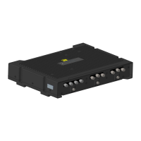
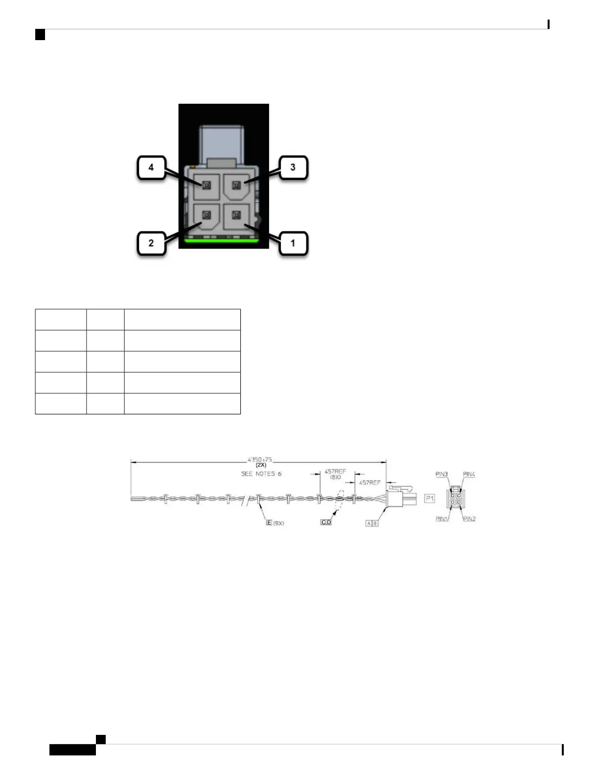
Figure 1: Power Connector Pinouts
Table 1: Power Connector Descriptions
DescriptionNamePin Number
DC Power Return (GND-)DC -1
CAN Bus Differential SignalCAN_P2
DC Power Input (12V, 24V)DC +3
CAN Bus Differential SignalCAN_N4
The IR1800 can be installed without connecting to the CAN Bus. There is a 2-wire cable that can be ordered
(CAB-PWR-15-MF4). The following is a diagram of the cable:
Verifying Connections
To verify that all the devices are properly connected to the router, turn on all the connected devices, and then
check the LEDs.
Connecting the Router
4
Connecting the Router
Verifying Connections