• There is no hardware mechanism to detect if an ODB II connector is attached
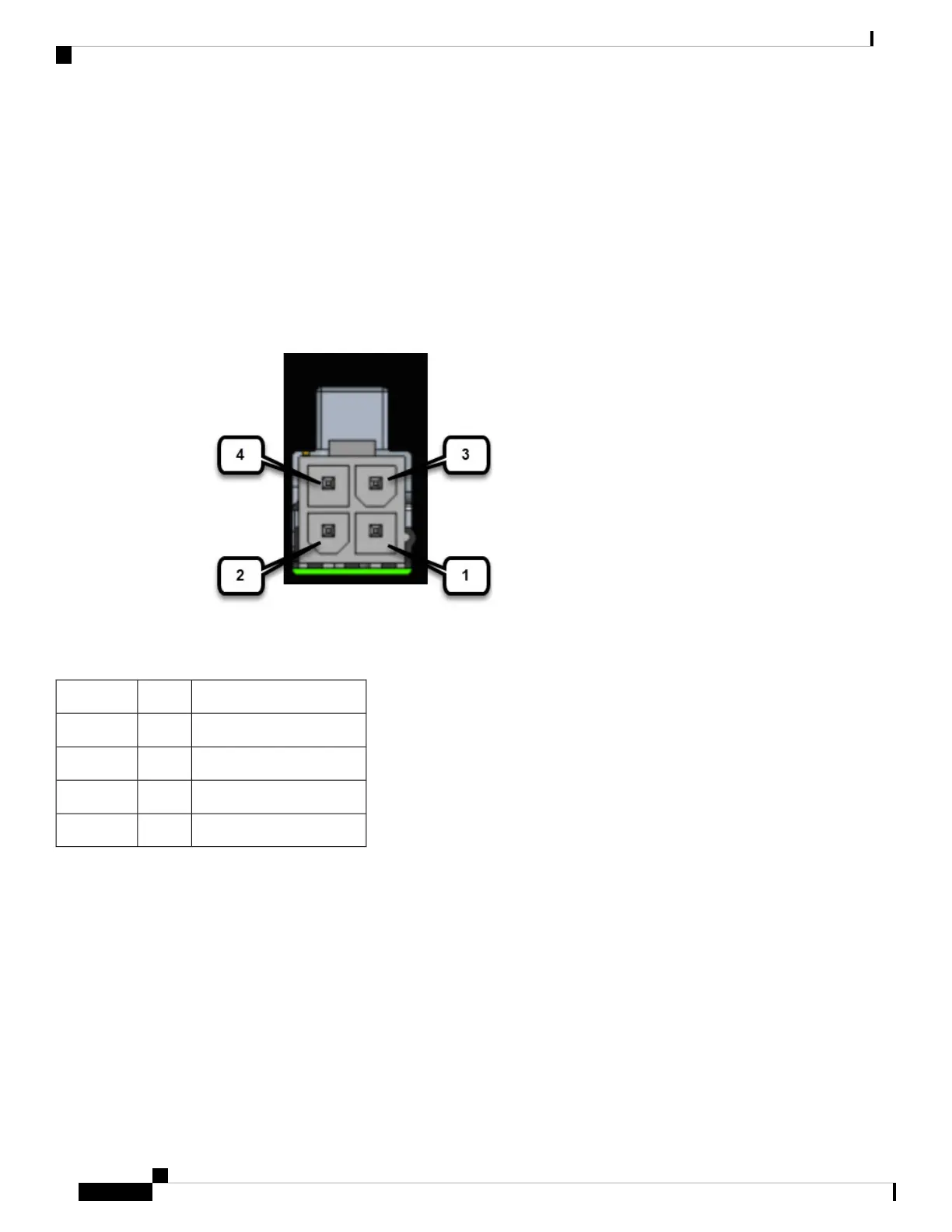
Can Bus Power Connector
The CAN_P and CAN_N signals are connected to two pins of the 4-pin mini-fit power connector. A cable can
be connected from the mini-fit connector to the OBD-II connector of the vehicle to get both unswitched power
and CAN interface input.
The pinouts are shown in the following figure.
Figure 26: Power Connector
Table 12: Power Connector Descriptions
DescriptionNamePin Number
DC Power Return (GND-)DC -1
CAN Bus Differential SignalCAN_P2
DC Power Input (12V, 24V)DC +3
CAN Bus Differential SignalCAN_N4
On-Board Diagnostic (OBD-II)
The following are some of the characteristics of On-Board Diagnostic (OBD-II):
• OBD or OBDI standardizes the connector so that it is identical in all the vehicles
• The communication protocol remains somewhat specific depending on the make of the vehicle
• The OBDII port is always powered up, even when the vehicle is turned off
• When connecting an IR1800 CAN Bus, the vehicles owner must review the characteristics of the ODB2
power and fuse protection
Cisco Catalyst IR1800 Rugged Series Router Hardware Installation Guide
62
Digital I/O, Ignition, and CAN Bus Connectivity
Can Bus Power Connector
 Loading...


