4-7
Cisco SCE8000 10GBE Installation and Configuration Guide
OL-21054-04
Chapter 4 Installing the Cisco SCE8000 Chassis
AC-Powered Systems
*The PDU power cable is designed for users who power their switch from a PDU. The end of the cable
that plugs into the Cisco SCE8000 chassis has a C19 connector; the other end of the cable that plugs into
the PDU has a C20 connector.
AC Power Cord Illustrations
This section contains the AC power cord illustrations.
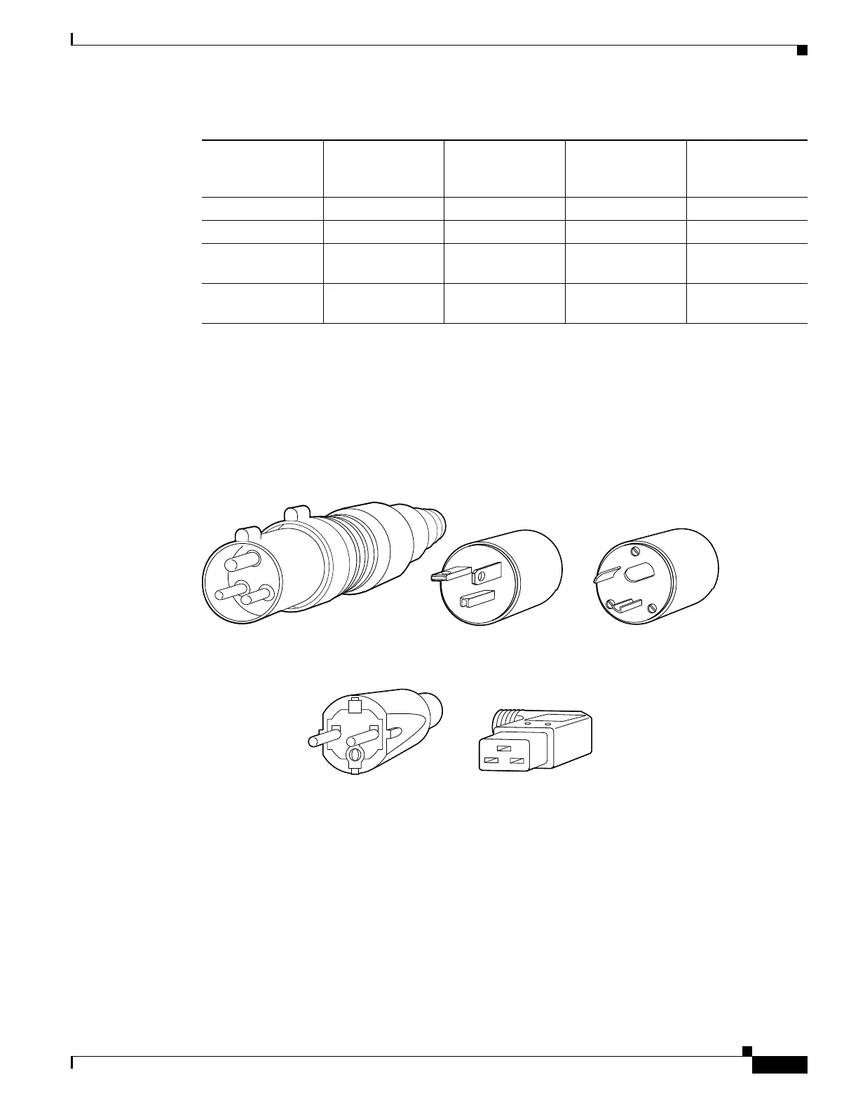
Figure 4-1 AC Power Cord Plugs and Appliance Coupler for the 2700 W Power Supply
South Africa CAB-7513ACSA= 14 feet (4.3 m) 250VAC, 16A Figure 4-9
Switzerland CAB-ACS-16= 14 feet (4.3 m) 250VAC, 16A Figure 4-10
Australia, New
Zealand
CAB-AC-16A-AU
S=
14 feet (4.3 m) 250VAC, 16A Figure 4-11
Power Distribution
Unit (PDU(=)*
CAB-C19-CBN 14 feet (4.3 m) 250VAC, 16A Figure 4-12
Table 4-4 AC-Input Power Cord Options (continued)
Locale Part Number Length Plug Rating
Power Cord
Reference
Illustration
68142
Europe
VIIG plug
CEE (7) VII (16A)
Appliance coupler
C19W coupler
Hot EN60320/C19 (20A)
North America (Locking)
(1900W power supply)
NEMA L6-20 plug (20A, 250V)
North America (Non-locking)
(1900W power supply)
NEMA 6-20 plug (20A, 250V)
International
(1900W power supply)
EN 60309 (16A, 250V)

 Loading...


