Americas Headquarters
Cisco Systems, Inc.
170 West Tasman Drive
San Jose, CA 95134-1706
USA
http://www.cisco.com
Tel: 408 526-4000
800 553-NETS (6387)
Fax: 408 527-0883
Cisco, Cisco Systems, the Cisco logo, and the Cisco Systems logo are registered trademarks or
trademarks of Cisco Systems, Inc. and/or its affiliates in the United States and certain other
countries. All other trademarks mentioned in this document or Website are the property of their
respective owners. The use of the word partner does not imply a partnership relationship between
Cisco and any other company. (0705R)
© 2009 Cisco Systems, Inc. All rights reserved.
78-18988-01
Connecting Network Devices
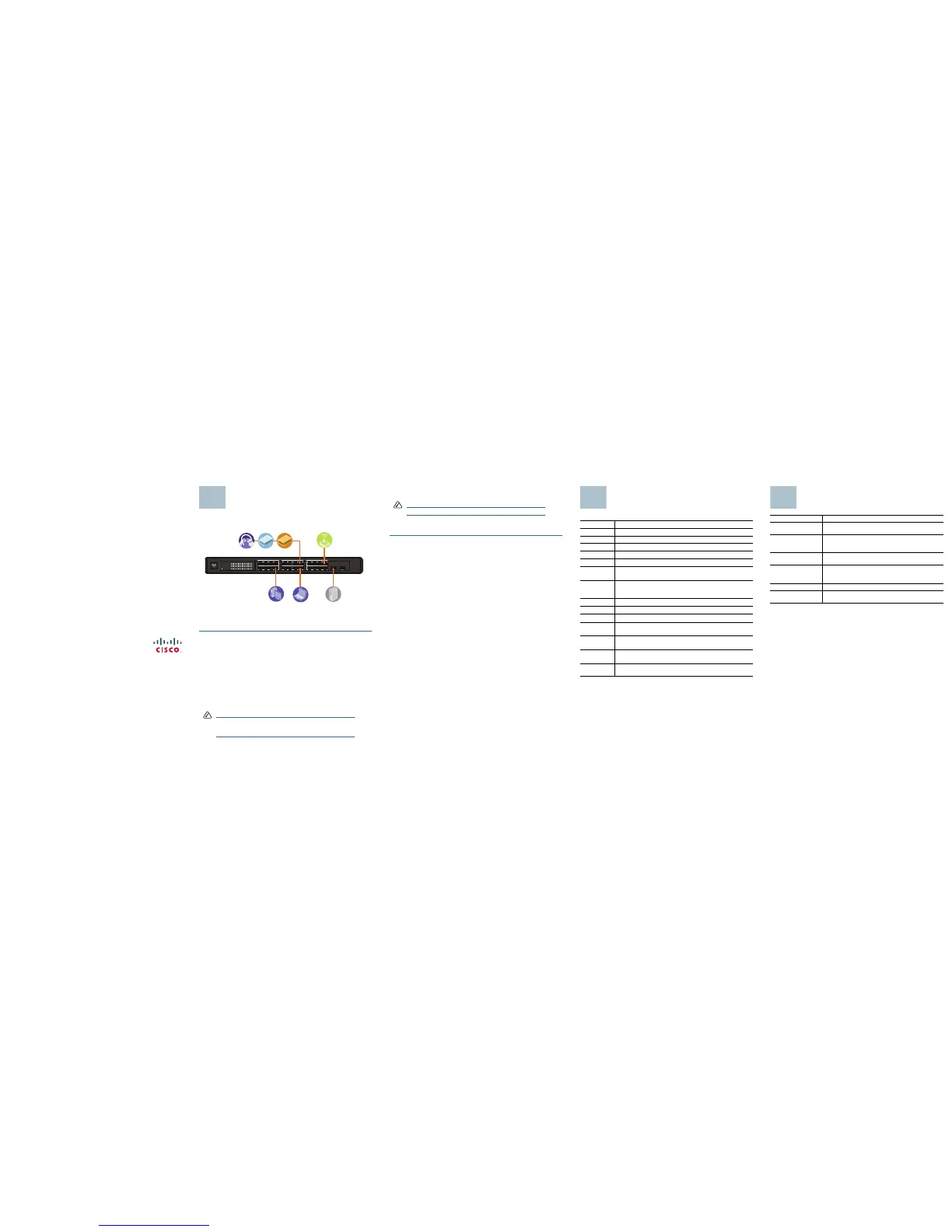
The following application diagram is an example of a typical network
configuration.
When you connect your network devices, make sure you do not exceed the
maximum cabling distance of 328 feet (100 meters).
Follow these steps to connect network devices to the switch:
STEP 1 Turn off all of the devices you want to connect to the switch.
S
TEP 2 Connect one end of a Category 5 Ethernet network cable to one of the
numbered ports on the switch. Connect the other end of the cable to a
computer or other network device.
S
TEP 3 Repeat Step 2 to connect additional devices.
S
TEP 4 If you are using a miniGBIC port, connect a miniGBIC module to the
miniGBIC port. The miniGBIC ports are shared.
• Do not use port 12 if you are using the miniGBIC1 port.
• Do not use port 24 if you are using the miniGBIC2 port.
For detailed instructions, refer to documentation for the module.
NOTE The miniGBIC ports are only compatible with the Cisco
miniGBIC models MGBSX1, MGBLH1, MGBT1, MGBLX1, and
MGBBX1.
1234 5678 9101112
13 14 15 16 17 18 19 20 21 22 23 24
miniGBIC1
(Shared with 12) (Shared with 24)
miniGBIC2
Cisco Small Business
SR2024
24-Port
10/100/1000 Swit ch
1 2 3 4 5 6 7 8 9 10 11 12 /
miniGBIC1
Link/Act
Gigabit
Link/Act
Gigabit
SYSTEM
13 14 15 16 17 18 19 20 21 22 23 24 /
miniGBIC2
193803
STEP 5 Connect the supplied power cord to the power port on the switch and
plug the other end into an electrical outlet.
NOTE When connecting power, always use a surge protector.
S
TEP 6 Power on the devices connected to the switch. The corresponding
LED for each active port will light up on the switch.
Congratulations! The installation of the SR2024 switch is complete.
Product Specifications
Feature Description
Model SR2024
Ports 24 RJ-45 10/100/1000 ports, two miniGBIC ports
Standards IEEE 802.3, 802.3u, 802.3x, 802.3ab
Cabling Type
Category 5 or better
LEDs
System, Link/Act 1-24, Gigabit 1-24
Security
Feature
Security slot
Dimensions
W x H x D
17.01 in. x 1.75 in. x 13.74 in.
(432 mm x 44.5 mm x 349 mm)
Unit Weight
7.98 lb (3.621 kg)
Power
100-127VAC/200-240VAC, 1.0A/0.5A, 50-60 Hz
Certification
FCC Class A, CE
Operating
Te m p e r a t u r e
32 to 104ºF (0 to 40ºC)
Storage
Te m p e r a t u r e
-4 to 158ºF (-20 to 70ºC)
Operating
Humidity
10% to 90%, noncondensing
Storage
Humidity
10% to 95%, noncondensing
Where to Go from Here
Resource Location
Te c h n i c a l
Documentation
http://www.cisco.com/en/US/products/ps10007/
tsd_products_support_series_home.html
Customer Support www.cisco.com/en/US/support/
tsd_cisco_small_business_support_center_contacts.
html
Open Source License
Notices
www.cisco.com/go/osln
Regulatory
Compliance and
Safety Information
www.cisco.com/en/US/products/ps10007/
tsd_products_support_series_home.html
Warranty Information www.cisco.com/go/warranty
Cisco Partner Central
site for Small Business
www.cisco.com/web/partners/sell/smb
 Loading...