6
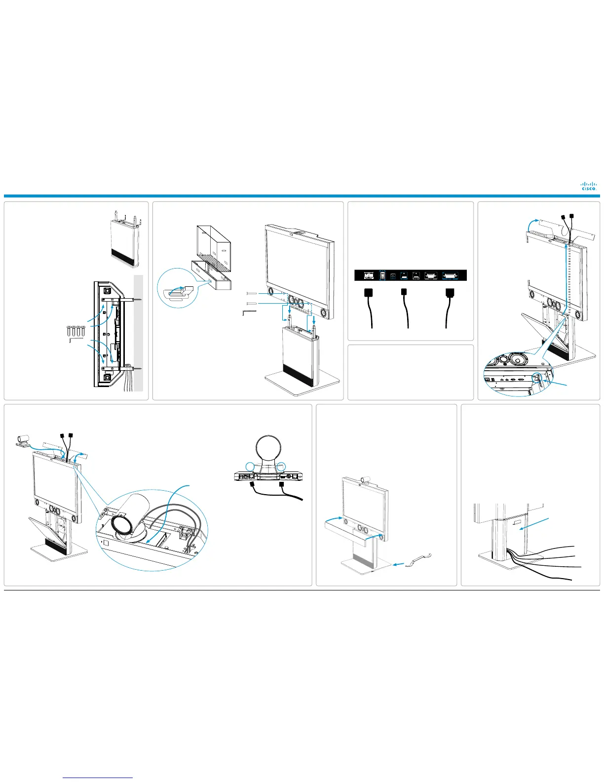
Connecting the monitor cables
1. Use the Allen key, which is found in the
foot module box, when fastening the wall
brackets to the bottom module with four
M6×10 screws.
2. Place the bottom module by the wall, mark
where to fasten the brackets and move
the bottom module away.
NOTE: Use a level to make sure the
system is mounted in an upright position.
Add a spacer between the wall bracket
and the wall if necessary.
3. Add the suitable fixing
device for the screws
in the wall.
4. Open the rear door. Locate and connect
the cables which are lead out of the
system at the rear side (the door will not
be accessible when the system is placed
by the wall).
5. Place the bottom module by the wall and
fasten it to the wall with proper screws.
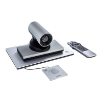
1. Connect the RJ45 and HDMI cables to the camera,
see illustration.
2. Place the camera on the bracket and slide it towards
the front.
3. Gently pull the cables down from inside the column to
organize the cables.
4. Close the top cover.
2. Push the camera cables up
the channel inside the monitor.
The entry to the cable channel
is underneath the monitor. You
can reach it inside the base
at the right hand corner (see
close-up illustration below).
Ethernet cable
PC cable
Microphone cables
Power cable
HDMIRJ45
HDMIRJ45
1. Open the top cover.
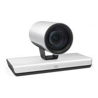
Camera cable configuration
PrecisionHD 1080p
HDMI
RJ45
For countries with 60 Hz current frequency
you must set the PrecisionHD 1080p camera
DIP switch to: 00100.
1. Open the rear door and lead the cables out the opening at the lower part
of the door. Connect the microphone cables if they are not pre-installed.
2. Close the rear door carefully. Take care not to shut the cables in the
door.
3. Place the PC cable and the microphones on the table.
4. Connect the Ethernet cable.
5. Connect the power cable (use the provided country specific cable).
6. Open the front door and turn on the monitor.
7. Follow the instructions in the accompanying Touch 8” installation
guide to connect and initialize the touch interface device.
8. The system should be up and running in a few minutes.
1. Use the level adjustment tool to adjust the height of the system to
make it stable (stand-alone foot module only).
2. Remove the plastic foil from the monitor.
3. Remove the plastic foil from the monitor frame.
4. Snap on the speaker grille to the front.
5. Use the supplied cloth to clean the system.
The rear door
LEVELLING ADJUSTMENT
Place the level adjustment
tool on the foot wheel under
the foot module for height
adjustment.
Seen from above, turn
clockwise to adjust the
height up. Use the opposite
side of the tool and turn
counterclockwise to adjust
down.
Cables
CAUTION: Due to the size and weight of this
equipment, it is very important that the wall
mount unit is safely installed according to the
installation instructions and that the wall is
able to safely support the product.
It is highly recommended that the wall
mounted system is installed by trained
personnel.
Push the camera
towards the front.
Locate the cables in the bottom module and connect them as
illustrated below.
1. HDMI cable
2. Speaker in, 15 pin D-SUB cable
(tighten the screws)
3. Power cable
Power HDMI 1 Speaker in
EMC A Class declaration
WARNING: This is a class A product. In a domestic environment
this product may cause radio interference in which case the user
may be required to take adequate measures.
Cable channel
entry point
5
Unpacking the Monitor box and mounting the monitor to the bottom module
1. Lift out to unlock and remove the snap lockers.
2. Lift up the monitor cover to unpack the
monitor.
3. Locate the speaker grille.
4. Carefully lift out the monitor and place it onto
the bottom module. It is recommended to be
two persons for this operation.
5. Insert the two M8×60 screws through the blue
marked holes in the speaker box.
6. Tighten the monitor gently to the bottom
module until the monitor cannot be moved
anymore.
Unpack
the monitor
box.
 Loading...