CHANNEL
A
(LEFT)
AND CHANNEL
B
(RIGHT)
OUTPUT
For
ease
of reference,
this
section
deals with only
the main
AB
Output
and does
not, therefore,
examine the
monitoring
facilities
or auxiliary
and
infil systems
found on both
mixers.
REAR
PANEL
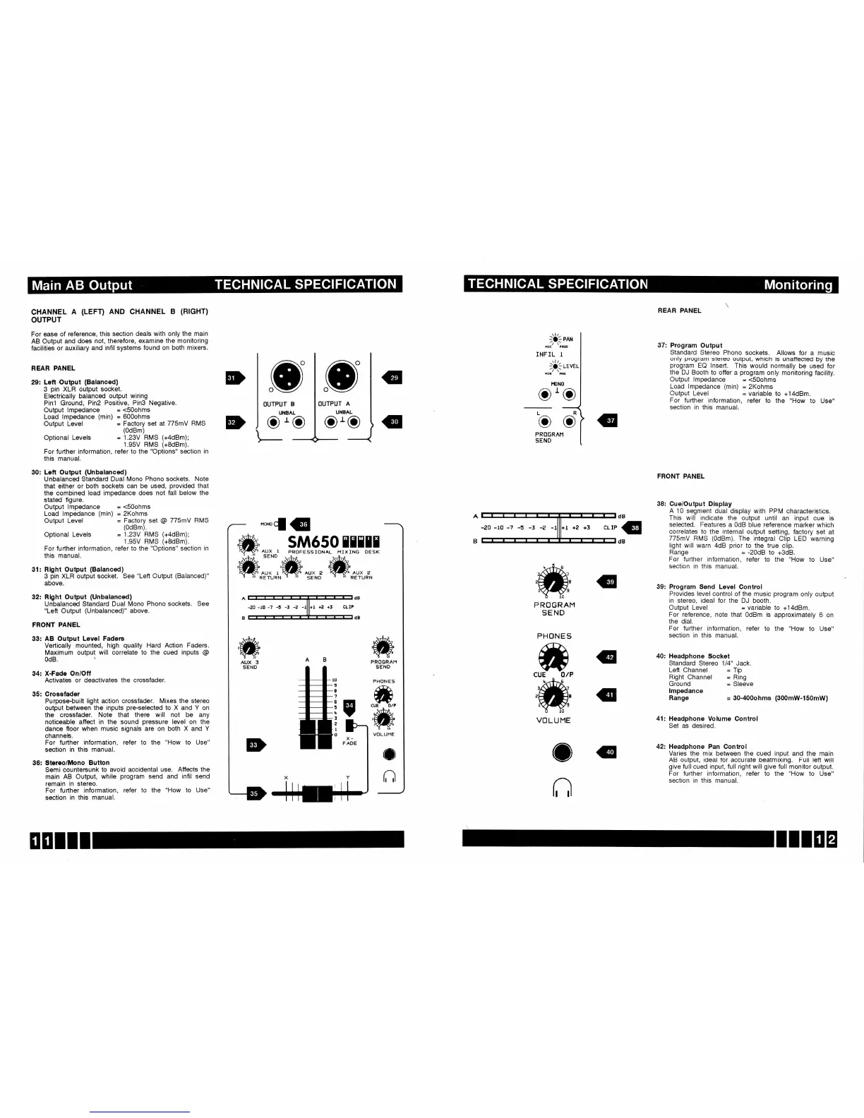
29: Left.Output
(Balanced)
3
pin
XLR output
socket.
Electrically
balanced
output wiring
Pinl Ground,
Pin2 Positive,
PinS Negative.
Output
lmpedance
=
<SOohms
Load lmpedance
(min)
=
600ohms
REAR PANEL
37:
Program
Output
Standard
Stereo
Phono
sockets.
Allows
for a
music
only
program
stereo output,
which is unaffected
by the
program
EQ lnseft.
This would normally
be used
for
the
DJ
Booth to offer
a
program
only
monitoring
facility.
Output
lmpedance
=
<S0ohms
Load lmpedance
(min)
=
2Kohms
O
OUTPUT
B
UNBAL
oro
o
o
Output
Level
=
variable
For
further information,
refer to
section
in
this manual.
to
+14dBm.
the
"How
to Use"
FRONT
PANEL
38: Cue/Output
Display
A 10
segment dual
display with PPM
characteristics.
This will indicate
the output until
an
input cue
is
selected. Features
a OdB blue
reference
marker
which
correlates to
the internal output
setting,
factory
set at
775mV
RMS
(0dBm).
The integral
Clip LED
warning
light
will warn 4dB
prior
to the true
clip.
Range
=
-20d8
to
+3dB.
For further
information,
refer to the
"How to
Use"
section
in this manual.
39: Program Send Level
Control
Provides level control
of the music
program
only
output
in stereo, ideal for the
DJ booth.
Output Level
=
variable to
+14dBm.
For reference,
note that OdBm is
approximately
6
on
the dial.
For
further information,
refer to the
"How
to
Use"
section
in this manual.
40:
Headphone Socket
Standard
Stereo 114" Jack.
Left
Channel
=
Tip
Right
Channel
=
Ring
Ground
=
Sleeve
lmpedance
Range
=
30-400ohms
(300mW-150mW)
41:
Headphone Volume Control
Set as
desired.
42: Headphone
Pan Control
Varies the mix between
the
cued input
and the
main
AB output, ideal for accurate beatmixing.
Full lett
will
give
full cued
input,
full right will
give
full
monitor output.
For further information, refer to
the
"How
to Use"
section
in this manual.
Output Level
Optional
Levels
For further
information,
this manual.
=
Factory
set at 775mY
RMS
(0dBm)
=
1.23V RMS
(+4dBm);
1.95V RMS
(+8dBm).
refer
to
the
"Options"
section
in
PRt]GRAH
SEND
P RO
GRAM
SEND
PHONE S
dB
G
dB
30: Left
Output
(Unbalanced)
Unbalanced Standard
Dual Mono
Phono sockets. Note
that either or
both sockets
can be used,
provided
that
the combined load impedance
does not fall
below the
stated figure.
Output
lmpedance
=
<S0ohms
Load lmpedance
(min)
=
2Kohms
Output
Level
=
Factory set
@
775mY
RMS
(0dBm).
Optional
Levels
For
further information,
this manual.
=
1.23V RMS
(+4dBm);
1.95V RMS
(+8dBm).
refer to the
"Options"
section
in
31: Rlght
Output
(Balanced)
3
pin
XLR output socket.
See
"Left
Output
(Balanced)"
above.
32: Rlght Output
(Unbalanced)
Unbalanced
Standard Dual
Mono
Phono sockets. See
"Left
Output
(Unbalanced)"
above.
FRONT
PANEL
33:
AB Output
Level Fadens
Vertically
mounted, high
quality
Hard Action Faders.
Maximum
output will correlate
to the cued inputs
@
34: X-Fade
Onioff
Activates
or deactivates the crossfader.
35:
Crossfader
Purpose-built
light action crossfader.
Mixes the stereo
output between
the inputs
pre-selected
to X and Y on
the crossfader.
Note that
there will not be any
noticeable
affect
in
the
sound
pressure
level on the
dance
floor when
music
signals
are on both X and
Y
channels.
For further
information, refer to the
"How
to Use"
section
in this
manual.
36:
Stereo/Mono
Button
Semi
countersunk
to avoid accidental
use. Atfects
the
main
AB Output,
while
program
send and
infil send
remain
in stereo.
For further
information,
refer to the
"How
to Use"
section
in
this manual.
ffi
AUX 3
SEND
PROGRAM
SENO
.ffi
ffii
O
r,l
CUE
OlP
ffi
VOLUME
o
r;l
",-;iq#
INF IL
I
)Litu*'
oro
 Loading...