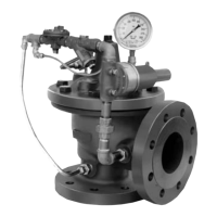
UL Listed Pressure Reducing Valve
INSTALLATION / OPERATION / MAINTENANCE
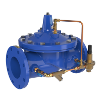
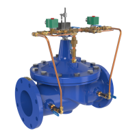
90G-21/90A-21 UL
MODEL
The Cla-Val 90-21 Pressure Reducing Valve is a pilot-operated regulator,
capable of holding downstream pressure to a predetermined pressure.
1. Special Note: For system protection, on valve sizes 1-1/2" thru 8" a
m
inimum 1/2" pressure relief valve is to be installed downstream (sys-
tem side) of the 90-21 Pressure Reducing Valve. For valve sizes 10" and
12" a 3" or larger relief valve is needed for the downstream side of the
90-21. Adequate drainage of the relief valve discharge must be provid-
e
d. The relief valve should be set above the “no flow” or “dead end” shut-
off pressure which is at 5 to 10 psi higher than the 90-21 set pressure
for 1-1/2" thru 8" valve sizes and 2 psi for 10" and 12" valve sizes.
2. Allow sufficient room around the valve assembly to make adjustments
and for disassembly.
3. It is recommended that isolation valves be installed on both ends of
the 90-21 valve to facilitate isolating the valve for start-up, testing and
preventative maintenance.
4. BEFORE THE VALVE IS INSTALLED, PIPE LINES SHOULD BE
FLUSHED OF ALL CHIPS, SCALE, AND FOREIGN MATTER.
5. Place the 90-21 valve in the line with flow through the valve in the
direction indicated on the inlet nameplate mounted on inlet flange or by
arrow on nameplate mounted on side of threaded ends valves. Check
all fittings and hardware for proper makeup and that no apparent dam-
age is evident.
6. Cla-Val valves operate with maximum efficiency when mounted in
horizontal piping with the cover UP; however, other positions are accept-
able. Due to size and weight of cover and internal components of six
inch and larger valves, installation with the cover up is advisable. This
makes periodic inspection of internal parts readily accessible.
Start-Up and Adjustment
1. Upon initial start-up and after any valve servicing, it is necessary to
follow these steps.
2. Prior to pressurizing the valve make sure the necessary gauges to
measure pressure are installed. Gauges should be installed upstream
(inlet) and downstream (outlet) of the valve. Unused ports on main valve
body can be used for this purpose.
Caution: During start-up and test procedures a large volume of water
may be discharged downstream. Check to make sure that the down-
stream venting is adequate to prevent damage to personnel and equip-
ment.
3. Close upstream and downstream isolation valves.
4. Slowly open the upstream isolation valve enough to allow the valve
and pilot control system to fill with liquid.
5. Bleed air from the main valve (1) cover and pilot system by slightly
loosening fittings or plugs at all high points until a steady flow of water
is observed retighten. It may be necessary to do this more than once.
6. Open fully the upstream isolation valve.
7. Slowly open the downstream isolation valve part way to establish a
low flow rate.
There must be liquid flowing through the valve during pressure
adjustments.
Optimum valve performance occurs when pressure setting is done with
flow rate as low as practical.
8.
Adjust the CRD Control (3) to desired pressure. To change pressure set-
ting, turn the adjusting screw in (clockwise) to increase delivery pressure.
Turn the adjusting screw out (counterclockwise) to decrease delivery pres-
sure.
The pressure should change approximately 27 psi per turn. Only
s
light changes in adjustment should be made to avoid damage to equip-
ment. When the desired setting has been made, tighten jam nut and
replace cover.
9. For 1-1/2" thru 8" 90-21 Pressure Reducing Valves the downstream
pressure relief control recommended set point is 2-8 psi above the CRD
(
3) set point. For 10" and 12" 90-21 Pressure Reducing Valves the set
point is 2 psi above the CRD (3) set point. The relief valve for the 10"
and 12" 90-21 should be installed a recommended minimum 6 pipe
diameters downstream of the 90-21
Maintenance
1. The Cla-Val 90-21 Pressure Reducing Valve requires no lubrication or
packing and a minimum of maintenance. However, a periodic inspection
schedule should be established to determine how the fluid handled is
affecting the efficiency of the valve. Minimum of once per year.
2. When servicing the pilot control system, use care to prevent damage.
If it is necessary to remove fittings or components, be sure they are kept
clean and replaced exactly as they were.
3. Repair and maintenance procedures of the Cla-Val Hytrol Main Valve
and pilot control components are included in a more detailed IOM man-
ual. It can be downloaded from our web site (www.cla-val.com) or
obtained by contacting a Cla-Val Regional Sales Office.
4. When ordering parts always refer to the catalog number and
stock number on the valve nameplate.
Main valve
fails to open
Main valve
fails to close
Fails to
Regulate
No pressure at valve inlet
Main valve diaphragm assembly
inoperative
Pilot Valve (CRD) not opening:
1. No. spring compression
2. Damaged spring
3. Spring guide not in place
4. Yoke dragging on inlet nozzle
Foreign matter between disc
and seat or worn disc. Scale on
stem or Diaphragm ruptured
Flow Clean Strainer plugged
Pilot Valve (CRD) remain open:
1. Spring compressed solid
2. Mechanical obstruction
3. Worn disc
4. Yoke dragging on inlet nozzle
5. Diaphragm damaged or loose
diaphragm nut. Leakage from
vent hole in cover
Air in main valve cover and/or
tubing
Pilot Valve (CRD) yoke dragging
on inlet nozzle
Check inlet pressure
Disassemble, clean and polish
stem, replace detective parts
1. Tighten adjusting screw
2. Disassemble and replace
3. Assemble properly.
4. Assemble properly
Disassemble main valve,
remove matter, clean parts and
replace defective parts
Remove and clean or replace
1. Back off adjusting screw
2. Disassemble and remove
obstruction
3. Disassemble remove and
replace disc retainer assembly
4. Assemble properly
5. Disassemble. replace
diaphragm and/or tighten nut
Loosen top cover plug and fit-
tings and bleed air
Assemble properly
SYMPTOM PROBABLE CAUSE REMEDY