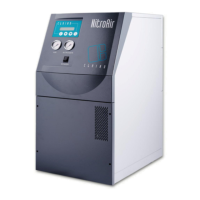
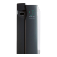
Nitrogen Generators Nitro35 Nitro70
11
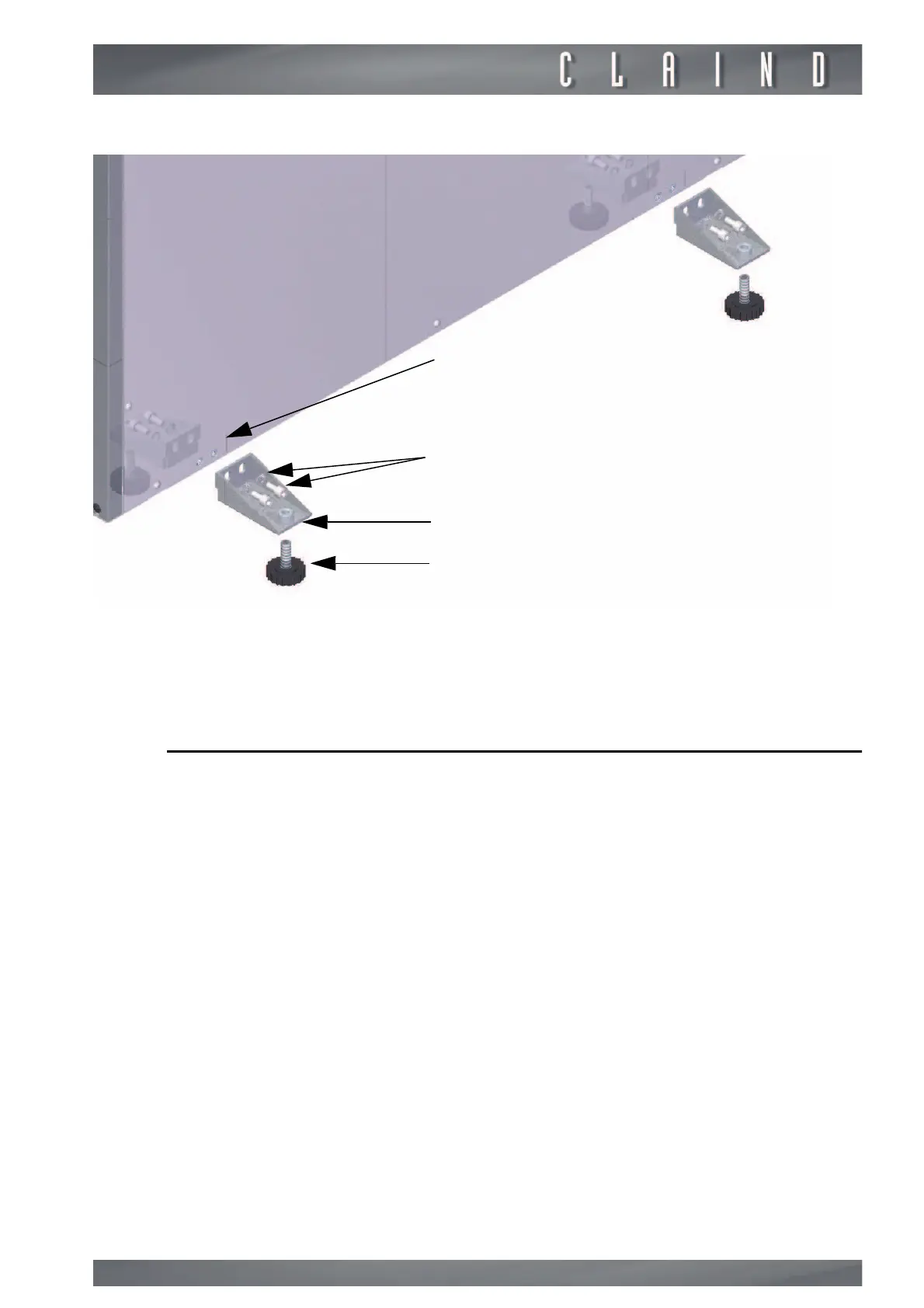
Use a allen key 4 mm to screw the feet and lift the generator from ground.
e
Claind disclaims any liability for damage to things, animals and people caused by
the overturning of generator caused by a lack of stabilizers.
4.3.
Pneumatic connections
The picture shows the elements that constitute a tipycal Nitrogen generation
plant. The fittings for pneumatic connection of the various components of the
plant (Nitrogen generator, compressed air reservoir, user) are located on the
back of the generator. The external air reservoir must be used only when the
tubes that connect it to the machine exceed 50 m lenght. It is possible to have
a longer line using tubes with nominal diameter > 8mm.