Description of the generator
8
3.3.
Elements of the generator
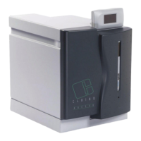
3.3.1.
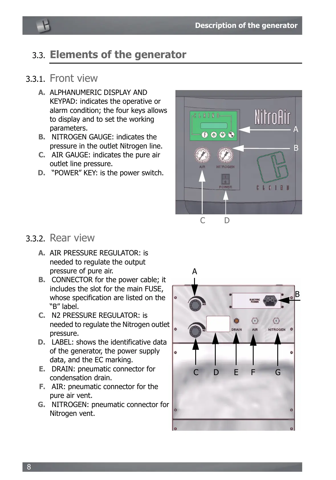
Front view
3.3.2.
Rear view
A. ALPHANUMERIC DISPLAY AND
KEYPAD: indicates the operative or
alarm condition; the four keys allows
to display and to set the working
parameters.
B. NITROGEN GAUGE: indicates the
pressure in the outlet Nitrogen line.
C. AIR GAUGE: indicates the pure air
outlet line pressure.
D. “POWER” KEY: is the power switch.
A. AIR PRESSURE REGULATOR: is
needed to regulate the output
pressure of pure air.
B. CONNECTOR for the power cable; it
includes the slot for the main FUSE,
whose specification are listed on the
“B” label.
C. N2 PRESSURE REGULATOR: is
needed to regulate the Nitrogen outlet
pressure.
D. LABEL: shows the identificative data
of the generator, the power supply
data, and the EC marking.
E. DRAIN: pneumatic connector for
condensation drain.
F. AIR: pneumatic connector for the
pure air vent.
G. NITROGEN: pneumatic connector for
Nitrogen vent.