5
Parts & Service: 020 8988 7400 / E-mail: Parts@clarkeinternational.com or Service@clarkeinternational.com
7. When the table is at its full height,
it should be possible to insert the
locking bar (F), through the hole in
the frame, (adjacent to the castor
mounting bracket), the
corresponding holes in each side
of the front lifting arm and out
through the opposite side of the
frame.
• The locking bar secures the
table to prevent any possibility
of it lowering while working,
and to provide a table working
platform.
8. Press the lowering lever (B) so that
the weight of the table is taken by
the locking bar.
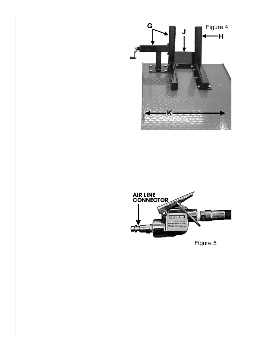
9. Attach the front wheel clamps (G & H) and stop Plate (J) in the manner
shown in Fig.4.
10. Attach the lashing eyes (K), - one to each side as shown in Fig. 4. The lift is
now fully assembled.
CML3AIR
1. Using all safety precautions with
regard to using air equipment -
(REFER TO THE AIR COMPRESSOR
MANUAL), connect a suitable air
hose equipped with a snap on
type connector to the hand
controller shown in Fig. 5.
• The hand controller is located
on the end of the hose leading
to the hydraulic ram.
2. Start the compressor with the outlet pressure set to zero and then open the
outlet valve.
3. Set the output pressure to between 8 - 13 bar, depending upon the
compressor size.
4. Press down the operating lever of the hand controller. The ram will begin to
operate and the platform will rise. Be prepared to release the lever
immediately should any part of the lift become snagged.
5. Raise the platform to its maximum height, then proceed as described in
para. 7.


 To Next Page