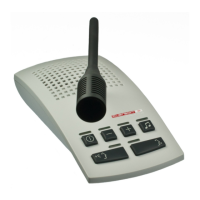
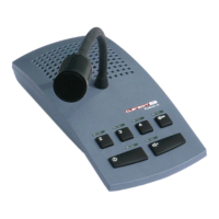
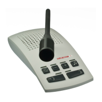
EasyManua.ls Logo

Clarson PUBLIC IV - User Manual

Clarson PUBLIC IV
6 pages
Print Icon
To Next Page IconTo Next Page
Loading...
PUBLIC IV
Intercom Ceiling LED
Service and Installaon Instrucons
Key funcons, LED signals ......................................................................................................................... 10
PTT mode .................................................................................................................................................. 10
Service sengs ......................................................................................................................................... 11
Volume control ......................................................................................................................................... 11
External connecons for headset, audio player, audio recorder .............................................................. 11
Installaon instrucons .......................................................................................................................... 4/5
Installaon intercom .............................................................................................................................. 6/7
Installaon intercom with footswitch..................................................................................................... 8/9
Installaon microphone ......................................................................................................................... 7/9
Installaon loudspeaker ......................................................................................................................... 7/9
Open duplex
Push-to-talk
Headset interface
Speech key control via footswitch
Music input
Recording possibility
AEC (Automac echo cancellaon)
NR (Noise reducon)
NG (Noise gate)
Individual volume control for loudspeaker / microphone/ headset /
audio via +/- keys
Balanced microphone inputs
Voltage/power ...................................................................................................................... 15VDC/700mA
Maximum power consumpon (limited by power supply) ................................................................ <15W
Power consumpon in OFF-mode ................................................................................................... <0.15W
Maximum output impedance (no connuous operaon) at 8Ω/channel .............................................. 5W
Minimum loudspeaker impedance .......................................................................................................... 8Ω
Audio IN-input level/input impedance ................................................................................... 30mV
(1)
/47k
REC OUT-output level/output impedance .............................................................................. 20mV
(2)
/10k
Temperature : ................................................................................................................................ 10 - 40 °C
Humidity: .....................................................................................................20 % to 75 % (non condensing)
Air pressure: ................................................................................................................ 700 hPa to 1060 hPa
(1)
Connect Audio IN to the headphone jack of the audio source.
Tune output level of the audio source in such a way that in case of maximum volume overmodulaon of the intercom system
is avoided.
(2)
This value depends on the volume set, on the speech volume and on the distance to the microphone.
35.054.440.007 07/2020
Table of Contents
Features
Technical Data
Question and Answer IconNeed help?

Do you have a question about the Clarson PUBLIC IV and is the answer not in the manual?

Overview

The Public IV Intercom Ceiling LED is a comprehensive communication system designed for various environments, particularly those requiring clear and reliable audio interaction between a control room and a patient's room. The system comprises several key components, including an intercom console, a ceiling-mounted microphone, a loudspeaker, and various connection hubs and power supplies.

Function Description:

The core function of the Public IV Intercom Ceiling LED is to facilitate two-way communication. The intercom console, typically located in a control room, serves as the central interface for managing communication with the patient's room. It features buttons for turning the intercom system ON/OFF, activating/deactivating the loudspeaker and microphone, and adjusting volume levels. The ceiling-mounted microphone in the patient's room captures speech, while the loudspeaker provides audio output.

The system supports a push-to-talk (PTT) mode, where transmission occurs only when a key is pressed, ensuring controlled communication. It also offers a push-and-hold key for switching the intercom system on and off, with LED indicators providing visual feedback on the system's status (ready for use, switched off, set-up mode, loudspeaker ON/OFF, microphone ON/OFF, audio IN/OFF).

The system is designed for ease of use and installation, with clear instructions for mounting and connecting all components. It supports various power supply options and includes necessary mounting materials for ceiling fixation of the microphone and loudspeaker, as well as for the connection hub and power supply.

Important Technical Specifications:

  • Voltage/power: 15VDC/700mA.
  • Maximum power consumption (limited by power supply): <15W.
  • Power consumption in OFF-mode: <0.15W.
  • Maximum output impedance (no continuous operation) at 8Ω/channel: 5W.
  • Minimum loudspeaker impedance: 8Ω.
  • Audio IN-input level/input impedance: 30mVeff/47kΩ.
  • REC OUT-output level/output impedance: 20mVeff/10kΩ.
  • Temperature: 10 - 40 °C.
  • Humidity: 20% to 75% (non condensing).
  • Air pressure: 700 hPa to 1060 hPa.
  • Dimensions intercom microphone cable: Length 1m, Ø 3.1mm.
  • External diameter, length 20m, Ø 5.5mm.
  • Clearance hole for RJ45 connector: minimum Ø16mm.
  • Dimensions loudspeaker cable: Length 20m, Ø 5.5mm.
  • Clearance hole for RJ45 connector: minimum Ø17mm.
  • Maximum speech distance to the microphone: 10cm.

Usage Features:

  • Simple Operation: The intercom console features intuitive buttons for managing communication. LEDs provide clear status indicators for various functions (system ON/OFF, loudspeaker ON/OFF, microphone ON/OFF, audio IN/OFF, volume levels).
  • Volume Control: Users can increase or reduce volume using dedicated buttons on the intercom console. The system supports maximum and minimum volume settings, indicated by LED flashes.
  • Adjustable Audio Settings: To avoid poor sound quality and feedback, it may be necessary to adjust the volume range settings to accommodate the acoustic conditions on site. This involves pressing specific button sequences to set the maximum volume for an optimal sound quality at the Control Room and Patient’s Room.
  • Headset Operation: After switching on the intercom system, the intercom console is activated, regardless of whether the headset microphone is plugged in or not. Switching to headset operation is made by removing and re-inserting the headset microphone plug.
  • Troubleshooting: In case of interference, intercom components should be relocated to increase the distance from sources of strong electromagnetic radiation.
  • Mounting Flexibility: The microphone is designed for ceiling fixation, positioned as close to the user's working position as possible, avoiding collision with other suspended components. The loudspeaker can be mounted on the ceiling above the user or on the wall below the ceiling behind the user. The intercom console should be placed as far from the control room door as possible.
  • Multiple Connection Options: The system supports various connections, including RJ45 connectors for intercom and microphone, and a power supply connection.
  • Push-to-Talk (PTT) Mode: This mode ensures controlled communication by activating transmission only when the PTT key is pressed.
  • Push-and-Hold Key: A push-and-hold key is used to switch the intercom system on and off, with LED indicators providing visual feedback.

Maintenance Features:

  • Modular Design: The system's components are modular, allowing for easier replacement or maintenance of individual parts.
  • Clear Installation Instructions: The manual provides detailed instructions for installation, including drilling templates for ceiling fixation and guidance on cable routing, which simplifies setup and potential troubleshooting.
  • Hook-and-Loop Fasteners: Mounting materials include hook-and-loop fasteners for the connection hub and power supply, facilitating secure yet accessible placement. These fasteners should only be used on suitable surfaces for proper adhesion.
  • Component Identification: Each component is clearly identified with labels and part numbers, aiding in inventory management and ordering replacement parts.
  • System Status Indicators: LED indicators on the intercom console provide immediate visual feedback on the system's operational status, helping to quickly identify any issues.
  • Cable Management: The system includes cable ties for organizing cables, contributing to a neat and maintainable installation.
  • Environmental Considerations: The device is designed to operate within specific temperature, humidity, and air pressure ranges, ensuring reliable performance in suitable environments.

Clarson PUBLIC IV Specifications

General IconGeneral
BrandClarson
ModelPUBLIC IV
CategoryIntercom System
LanguageEnglish

Related product manuals