EasyManua.ls Logo

Clarson PUBLIC III CE User Manual

Clarson PUBLIC III CE
6 pages
To Next Page IconTo Next Page
Page #1 background imageLoading...
Page #1 background image
PUBLIC III CE
Intercom System Comfort Edion
Service and Installaon Instrucons
Key funcons, LED signals ......................................................................................................................... 10
PTT mode .................................................................................................................................................. 10
Service sengs ......................................................................................................................................... 11
Volume control ......................................................................................................................................... 11
External connecons for headset, audio player, audio recorder .............................................................. 11
Installaon instrucons .......................................................................................................................... 4/5
Installaon intercom .............................................................................................................................. 6/7
Installaon intercom with footswitch ..................................................................................................... 8/9
Installaon microphone ......................................................................................................................... 7/9
Installaon loudspeaker ......................................................................................................................... 7/9
Open duplex
Push-to-talk
Headset interface
Speech key control via footswitch
Music input
Recording possibility
AEC (Automac echo cancellaon)
NR (Noise reducon)
NG (Noise gate)
Individual volume control for loudspeaker / microphone/ headset /
audio via +/- keys
Balanced microphone inputs
Voltage/power ...................................................................................................................... 15VDC/700mA
Maximum power consumpon (limited by power supply) ................................................................. <15W
Power consumpon in OFF-mode ................................................................................................... <0.15W
Maximum output impedance (no connuous operaon) at 8Ω/channel ............................................... 5W
Minimum loudspeaker impedance .......................................................................................................... 8Ω
Audio IN-input level/input impedance .......................................................................... max. 100mV
(1)
/2k
REC OUT-output level/output impedance ............................................................................. max.3V
(2)
/2k
Temperature : ............................................................................................................................... 10 - 40 °C
Humidity: .................................................................................................... 20 % to 75 % (non condensing)
Air pressure:................................................................................................................. 700 hPa to 1060 hPa
(1)
Connect Audio IN to the headphone jack of the audio source.
Tune output level of the audio source in such a way that in case of maximum volume overmodulaon of the intercom system
is avoided.
(2)
This value depends on the volume set, on the speech volume and on the distance to the microphone.
35.054.012 07/2015
Table of Contents
Features
Technical Data
Question and Answer IconNeed help?

Do you have a question about the Clarson PUBLIC III CE and is the answer not in the manual?

Clarson PUBLIC III CE Specifications

General IconGeneral
BrandClarson
ModelPUBLIC III CE
CategoryIntercom System
LanguageEnglish

Summary

Key Functions, Connections, and LED Signalling

External Connections Central Unit

Details external connection options for the Central Unit, including audio recorder.

External Connections Intercom Console

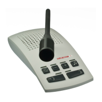
Details external connection options for the Intercom Console, including audio player and headset.

Operational Start-up and Service

Guidance on initial system setup, volume adjustments, and operational best practices.

PTT Mode Operation

Instructions for activating and deactivating push-to-talk (PTT) mode.

Troubleshooting Interferences

Recommendations for resolving interference issues by repositioning components.

Delivery Contents

Intercom System Components

Lists various components included in the intercom system delivery, such as consoles, speakers, and microphones.

Footswitch Delivery Contents

Details the components included for footswitch functionality, including adapters and cables.

Mounting Material and Component Positioning

Mounting Material for Components

Details the specific mounting hardware required for microphones, central units, loudspeakers, and power supplies.

Microphone Installation

Guidelines for ceiling fixation of the microphone, emphasizing placement relative to the user and other components.

Loudspeaker Installation

Recommendations for loudspeaker placement to avoid interference, suggesting wall mounting and optimal height.

Intercom Console Placement

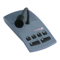
Guidance on positioning the intercom console, focusing on distance from the control room door and optimal speech distance.

Installation Schematics and Planning

Central Unit Installation

Instructions and diagrams for installing the central unit on a wall or under a table.

Loudspeaker Installation Planning

Provides diagrams and notes for planning loudspeaker installation, including fixation areas and distances.

Ceiling Microphone Installation

Details for ceiling installation of the microphone, including use of a drilling template.

Installation Cable Lengths

Important planning information regarding microphone and loudspeaker cable lengths and connector clearance holes.

System Wiring and Connections

Control Room Wiring (Without Footswitch)

Diagram illustrating the wiring and connections for the intercom system in the control room without a footswitch.

Patient's Room Installation

Shows the installation of the loudspeaker and ceiling microphone in the patient's room.

Central Unit Installation Details

Specific instructions and diagrams for installing the central unit, including power and data connections.

System Wiring with Footswitch

Control Room Wiring (With Footswitch)

Diagram showing the wiring and connections for the intercom system in the control room, including footswitch.

Patient's Room Installation (Footswitch System)

Illustrates the installation of loudspeaker and microphone within the patient's room for a footswitch-enabled system.

Installation Planning Details

Provides essential planning information regarding cable lengths and connector sizes for installation.

Related product manuals