6 7
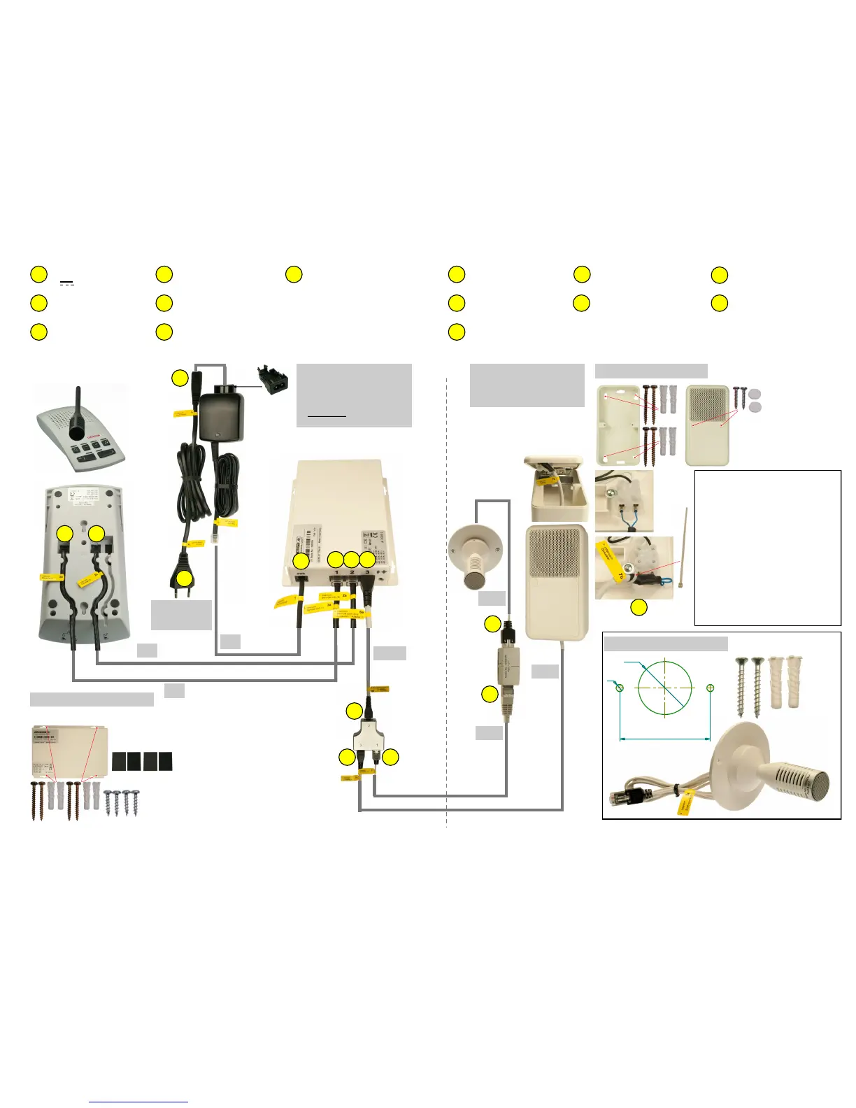
> Intercom Cleaner Socket
< Intercom Power Supply
> Intercom Power Supply
< Intercom Cleaner Socket
> Intercom Central Unit
(DC Power)
> Intercom Central Unit (1)
< Intercom Console (1)
> Intercom Console (1)
< Intercom Central Unit (1)
> Intercom Console (2)
< Intercom Central Unit (2)
> Intercom Central Unit (2)
< Intercom Console (2)
1
1a
1b
2a
2b
3a
3b
2a 3a
1
6a
1b
1a
2b 3b
6b
7a 8
> Intercom Central Unit (3)
< Intercom T-Adapter (2)
> Intercom T-Adapter (2)
< Intercom Central Unit (3)
> Intercom T-Adapter (3)
< Intercom Speaker
> Intercom Speaker
< Intercom T-Adapter (3)
7a
7b 6a
6b
Important for Installaon Planning:
Dimensions microphone cable :
Length 1m, Ø 2,6mm
Extension cable length 20m, Ø 5,5mm
Clearance hole for RJ45 connector
minimum Ø16mm.
Observe drilling template!
Dimensions loudspeaker cable:
Length 20m, Ø 5,5mm
Clearance hole for RJ45 connector
minimum Ø17mm.
Dimensions mounng material
see page 4
Wandsteckdose
100-240V
50-60Hz
~
7b
H
C
C
N
Use hook-and-loop
fasteners only on suitable
surface (adhesion)!
O
F
C C
or
O
On the wall or under the table
wall socket
100-240V
50-60Hz
~
Installaon Loudspeaker
Paent´s Room
30cm
Control Room
Intercom System
without footswitch
2m
3m
3m
Installaon Central Unit
No other power supply than the one tested and appro-
ved by Clarson must be used.
> Intercom T-Adapter (1)
< Intercom RJ45 Connector (2)
8
> Intercom RJ45 Connector (1)
8a
> Intercom R45 Connector (2)
< Intercom T-Adapter (1)
8b
Ceiling installaon microphone