GREAT BRITAIN
Digital Multimeter Article number: 36-1743 • Model: BS1801
• Digital Multimeter BS1801 with 3½ - digit display.
• Automatic shutdown
• Comes with test probes and 9V battery, type 6F22.
1. Warning!
The instrument is meant for indoor use at temperatures 5ºC - 40ºC at a height up
to 2000 m above sea level.
Follow all instructions for safety and use in the instruction manual.
• Carefully read the following before you start to use the meter.
• Avoid damage to the meter by not exceeding maximum input values for the
measuring data.
• Do not use the meter or test cables if they look like they are damaged. Be
very careful when you work close to uninsulated cable.
• Accidental contact with electric cables can give electric shocks.
• Only use the meter the way described in this instruction manual.
• Read the entire instruction manual before use. Follow all safety instructions.
• Be careful when working with voltages greater then 20 V DC they can give
electric shocks.
• Remember to disconnect the circuit from the mains and all loads from the
circuit before measuring resistance and continuity testing.
• Never use the meter if it is damaged or does not work correctly.
2. Safety symbols
!
Read the manual before use
AC current
DC current
Measuring diodes
Continuity test
Earth
The meter is protected by double insulation
Conforms to CE norms
The instrument is constructed and tested according to the EN publication norms:
61010-1, environmental class II and installation category III 600 V.
The instrument is tested according to the following EC directive:
• 89/336/EEC Electromagnetic Compatibility, EN61326
• 73/23/EEC Product safety law of Low Voltage Directive, EN61010-1
3. Functions
• 3 ½ digit LCD display with max. reading 1999
• 600 V AC/DC voltage range
• 30MΩresistancerange
• Continuity test with buzzer
• Automatic polarity indication
• Memory for current or max. value
• Automatic zeroing
• Automatic shutdown after 15 minutes inactivity
• Overvoltage warning: Only the digit “1” is displayed
3.1 This box contains
• 2 x test leads
• Instruction manual
• Multimeter
• 9 V battery
• Test protocol
4. Electrical Specications
Accuracyis±(%ofreading+amountoftheleastsignicantnumber)at23°C±
5°C,<75%RH.
DC V
Measurement
Range
Resolution Accuracy Input
Impedance
Overload Protection
200 mV 0.1 mV ±(0,8%+1) 10MΩ 600V DC/AC rms
2 V 1 mV ±(0,8%+1) 10MΩ 600V DC/AC rms
20 V 10 mV ±(0,8%+1) 10MΩ 600V DC/AC rms
200 V 100 mV ±(0,8%+1) 10MΩ 600V DC/AC rms
600 V 1 V ±(1.0%+1) 10MΩ 600V DC/AC rms
ACV
Measurement
Range
Resolution Accuracy Input
Impedance
Overload
Protection
Frequency
200 V 100 mV ±(1,5%+10) 10MΩ
600V DC/AC rms
40–400Hz
600 V 1 V ±(1,5%+10) 10MΩ
600V DC/AC rms
40–400Hz
DC A
Measurement
Range
Resolution Accuracy Voltage
drop
Overload Protection
200 mA 0.1 mA ±(1,0%+3) 100 mV Fuses:200mA/250V(quick)
10 A 100 mA ±(2,0%+5) 100 mV Fuses:10A/250V(quick)
Resistance Ω
Measurement
Range
Resolution Accuracy Idling
voltage
Overload Protection
200Ω 0,1Ω ±(1.0%+5) ≤0.7V 250VDC/ACrms(<10s)
2kΩ 1Ω ±(1.0%+5) ≤0.7V 250VDC/ACrms(<10s)
20kΩ 0.01kΩ ±(1.0%+5) ≤0.7V 250VDC/ACrms(<10s)
200kΩ 0.1kΩ ±(1.0%+5) ≤0.7V 250VDC/ACrms(<10s)
20MΩ 0.01MΩ ±(1.5%+3) ≤0.7V 250VDC/ACrms(<10s)
Diode Test
Measurement
Range
Test
voltage
Test current Idling
voltage
Overload Protection
0-1999 mV 1.0±0.6 mA Approx.
2.8 V
250VDC/ACrms(<10s)
Continuity Test
Measurement
Range
Test range Test current Idling
voltage
Overload Protection
<50±30Ω* 1.0 mA Approx.
2.8 V
250VDC/ACrms(<10s)
*buzzersoundsat<50±30Ω
Battery Test
Measurement
Range
Test current Overload Protection
1.5 V 40mAat37Ω Fuses:200mA/250V(quick)
9V mA 24mAat361Ω Fuses:10A/250V(quick)
4.1 Specifications
Display: 3 ½ digit LCD display with max. reading 1999.
Indication of polarity: Automatic, the display shows “-” for negative polarity.
Zeroing: Automatic
Indication that the value is outside the measurement range:
The display will show “1”.
PowerSupply: 1x9Vbattery(6LR61)
Automatic shutdown: 15 minuter
Sizeinmm: 150x80x40(hxbxd)
Weight: Approx. 300 grams with battery
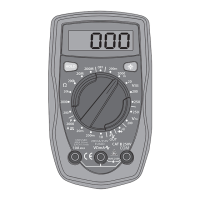
5. Description
1. 3½ digit display
2. [RES] Reset button
3. [HOLD]Memorybutton
4. Function selector
5. Test probe connection
6. Use
If the display does not change while measuring you should check that the Data
Holdisnotactivated(“H”isshownonthedisplaywhenHoldisactivated)
6.1
Measuring DC Voltage (VDC) and AC Voltage (VAC)
1. Connect the black test lead to the “COM” jack and the red test lead to the
“V/Ω”jack.
2. Set the function selector to DCV or ACV and connect the test probes to the circuit.
3. Readthevalue,press[HOLD]ifyouhavedifcultyseeingthedisplayorifyou
wish to save the reading.
6.2 Measuring DC Current (DCA)
1. Connect the black test lead to the “COM” jack and the red test lead to the
“mA”jack(formeasurementsupto200mA).
2. Set the function selector to “200m” and connect the test probes to the circuit.
3. Readthevalue;press[HOLD]ifyouhavedifcultyseeingthedisplayorifyou
wish to save the reading.
4. Measuringcurrentstrengthsfrom200mAto10A(fused)isdoneinthesame
way but the red test lead is connected to “10A”.
Warning! Maximumoverload:250VDC/ACrms(<10s).
6.3 Measuring Resistance (Ω)
1. Check that the circuit is not carrying any current and discharge all capacitors
before measuring.
2. Settheselectorswitchtothedesiredmeasuringrange(200Ω-20MΩ)
3. Connect the black test lead to the “COM” jack and the red test lead to the
“V/Ω”jack.
4. Connect the probes to the circuit and read displayed value.
5. Readthevalue;press[HOLD]ifyouhavedifcultyseeingthedisplayorifyou
wish to save the reading.
Warning! Maximumoverload:250VDC/ACrms(<10s).
6.4 Diode Test
1. Connect the black test lead to the “COM” jack and the red test lead to the
“V/Ω”jack.
2. Set the selector switch to .
3. Connecttheblacktestprobetothecathode(-)andtheredtestprobetothe
anode(+)onthediodeandreadthedisplayedvalue.
4. Read the voltage drop across the diode (if the test leads have been
connectedincorrectly“1”appearsinthedisplay).
6.5 Continuity Test
1. Set the selector switch to .
2. Connect the black test lead to the “COM” jack and the red test lead to the
“V/Ω”jack.
3. Connect the test probes to the circuit.
4. Iftheresistanceislessthan50±30Ωthebuzzerwillactivate!
6.6 Battery Test
1. Set the selector switch to 1.5V or 9V depending on which battery is to be
tested1.5V(forR69)or9V(for6LR61).
2. Connect the black test lead to the “COM” jack and the red test lead to the
“mA” jack.
3. Connectthetestprobestothebattery(redto+andblackto-).
4. The capacity of the battery is displayed (a good value for R6 batteries is 40mA
andfor6LR61batteriesis24mA).
6.7 Switching the multimeter off
• Turn the selector switch to “OFF”.
• Automatic shutdown after 15 minutes inactivity. Push [RES] to turn on the
instrument after automatic shutdown.
6.8 Memory
Currentreadingmemoryallowsyoutosavereadings.Push[HOLD]tosavethereading,
push[HOLD]oncemoretoerasethememoryandtakeanewmeasurement.
7. Battery change
Warning: Always remove the
test cables from the circuit before
changing batteries.
1. Check that the instrument is not
connected to any test object.
Remove the test cables and set
the function selector to “OFF”.
2. Remove the screw that holds
the battery cover on the back of
the instrument.
3. Remove the old battery and insert a new one as marked in the battery compartment.
4. Putthebatterycoverbackandtightenthescrew.Note!Donottightentoo
hard, the housing can be damaged.
8. Replacing the fuses
Warning: Always remove the
test cables from the circuit before
changing batteries. Always replace
fuses with identical ones.
1. Check that the instrument
is not connected to any test
object. Remove the test
cables and set the function
selector to “OFF”.
2. Remove the four screws
securing the back panel of
the instrument.
3. Remove the battery and take off the back.
4. Youwillseeafuse,itisa200mAfuse(5x20mm,quick)
5. The 10A fuse is located on the circuit board under the 200mA fuse, unscrew
the nine small screws to get at it.
6. Putthebatterycoverbackandtightenthescrews.Note!Donottightentoo
much!
Note! Check that the function selector is on “OFF” before replacing the circuit
board.
9. Cleaning
• Wipe off with a damp cloth when needed
• Only use mild detergents, never solvents or strong detergents.
Warning! Avoid exposing the instrument to electric shocks, knocks and water.
10. Disposal
• Electrical waste products must not be thrown away with household waste.
• Follow local ordinances when disposing of this product. If you are unsure
about how to dispose of this product contact your municipality.