AUTOMATIC WHEEL BALANCER 3D WITH LCD SCREEN
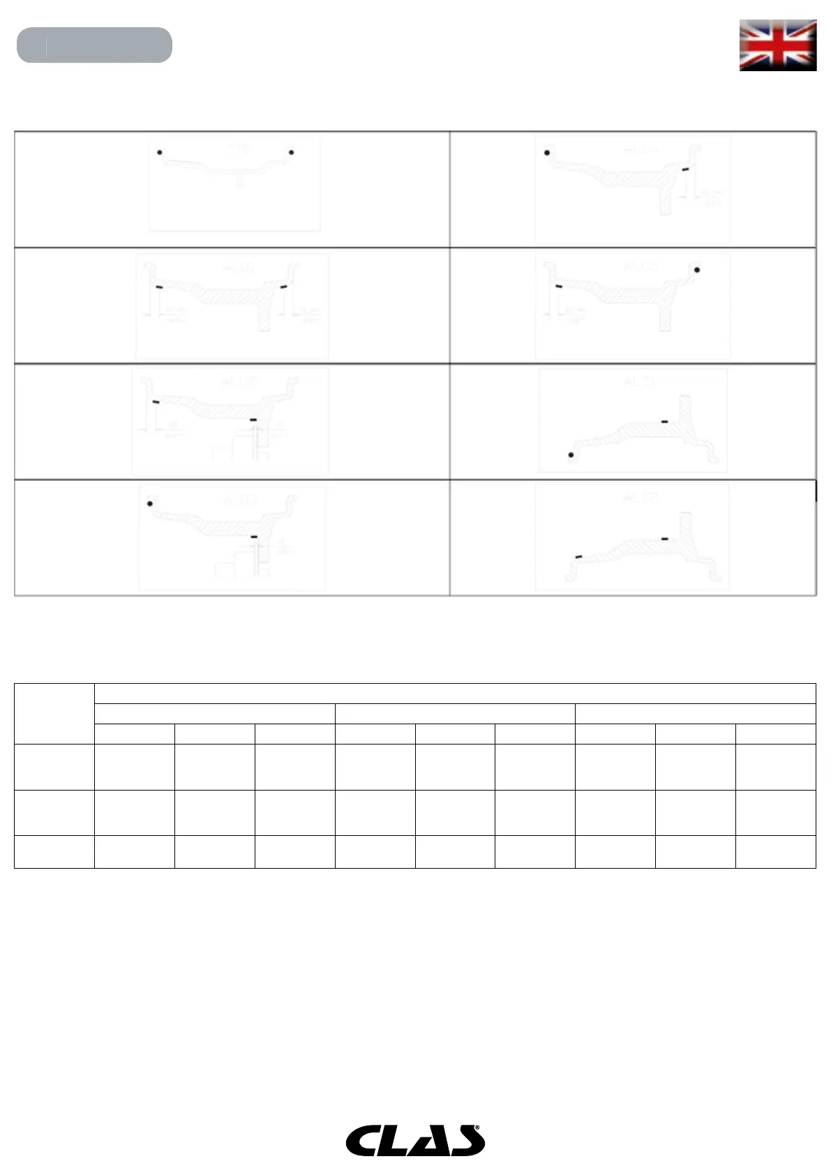
Position of the weights in the various Program Types along the section of the rim
Angular position of the balancing weights in the various Program Types
Note (1): if the data acquisition system is disabled, the angular position of the weight will be in the 6 o’clock position.
In table T15.2 the symbol “H12” indicates that the angular position of the weight is at 12 o’clock while the symbol
“H6” indicates that the angular position of the weight is at 6 o’clock.
The machine data acquisition systems are dened as follows:
• Semi-automatic when the Distance and Diameter data are automatically acquired with the Distance/Diameter
sensor while the data on the width must be manually entered;
• Automatic when all data of the rim is automatically acquired with the two sensors.
Machine data
acquisition
system
Program Type
STD, ALU1,2,3,4,5 ALS1 ALS2
Internal plane External plane Static plane Internal plane External plane Static plane Internal plane External plane Static plane
Semi-
automatic
H12 H12 H12 H12 Sensor-rim
contact
point(1)
H6 Sensor-rim
contact
point(1)
Sensor-rim
contact
point(1)
H6
Automatic H12 H12 H12 H12 Sensor-rim
contact
point(1)
H6 Sensor-rim
contact
point(1)
Sensor-rim
contact
point(1)
H6
Laser H12 H12 H12 H12 H6
Sticker
H6 H6
Sticker
H6
Sticker
H6