EasyManua.ls Logo

Class 1 TPG+ - User Manual

Class 1 TPG+
2 pages
Print Icon
To Next Page IconTo Next Page
Loading...
Total Pressure Governor Plus (TPG+)
OEM Quick Manual
TPG+ OEM Quick Manual P/N 118712
REV A
05-16-2018
INSTALLATION
Mount the TPG+ on the operator’s panel with four #10 screws.
The dimensions in the detail below are in inches [millimeters].
WIRING HARNESS
The main system harness (p/n 118453) is comprised of a pair of harnesses:
the power/communication harness (depicted below in blue) and the signals
harness (depicted below in green).
For the analog control option, add harness wires (p/n 118454) depicted in
red.
DISCHARGE PRESSURE TRANSDUCER INSTALLATION
Install the 300 psi (2068 kPa, 20 bar) discharge pressure
transducer (p/n 113557) on the discharge side of the pump.
The pressure connection is a ¼-18 NPT male port. A ‘T’ fitting
can be used to share the pressure gauge outlet on the
discharge manifold.
INTAKE PRESSURE TRANSDUCER INSTALLATION
Install the 300 psi (2068 kPa, 20 bar) intake pressure
transducer (p/n 113557) on the intake side of the pump. The
pressure connection is a ¼-18 NPT male port.
VERIFY ENGINE RPM
Verify proper J1939 CAN connection to the engine’s ECM by
monitoring the RPM display of the TPG+ while the engine is
running. The display should show accurate RPM information.
VERIFY INTERLOCKS
The TPG+ requires OEM provided interlocks THROTTLE READY and PUMP ENGAGED for proper operation. The TPG+ utilizes backlit text to
indicate interlock status. The interlock status indicators are located directly beneath the switch panel.
Activate the throttle ready interlock. (Apply system power to pin 2 of connector C4).
Verify the THROTTLE READY text illuminates.
The TPG+ will operate in RPM mode only and cannot be changed to pressure mode.
Activate the pump engaged interlock. (Apply system power to pin 10 of connector C4).
Verify the PUMP ENGAGED text illuminates.
The TPG+ will not operate in any mode without the THROTTLE READY interlock.
Activate the throttle ready and pump engaged interlocks. (Apply system power to pins 2
and 10 of connector C4).
Verify the PUMP ENGAGED, OKAY TO PUMP, and THROTTLE READY text
illuminates.
The TPG+ will operate in either mode.
Question and Answer IconNeed help?

Do you have a question about the Class 1 TPG+ and is the answer not in the manual?

Summary

Installation

Mounting the TPG+

Mount the TPG+ on the operator's panel with four #10 screws. Dimensions are in inches [millimeters].

Wiring Harness

System Harness Description

The main system harness (p/n 118453) includes power/communication and signals harnesses.

Analog Control Harness

For analog control, add harness wires (p/n 118454) as depicted.

Discharge Pressure Transducer Installation

Discharge Pressure Transducer Installation

Install the 300 psi discharge transducer (p/n 113557) on the pump discharge side using a 14-18 NPT male port.

Intake Pressure Transducer Installation

Intake Pressure Transducer Installation

Install the 300 psi intake transducer (p/n 113557) on the pump intake side using a 14-18 NPT male port.

Verify Engine RPM

Verify J1939 CAN Connection

Verify J1939 CAN connection by monitoring accurate RPM display on TPG+ while engine is running.

Verify Interlocks

Required Interlocks

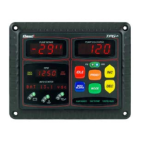
TPG+ requires THROTTLE READY and PUMP ENGAGED interlocks for operation, indicated by backlit text.

Verify Throttle Ready Interlock

Activate throttle ready interlock (power pin 2, C4) and verify THROTTLE READY text illuminates.

Verify Pump Engaged Interlock

Activate pump engaged interlock (power pin 10, C4) and verify PUMP ENGAGED text illuminates.

Verify Combined Interlocks

Activate both interlocks (pins 2 & 10, C4) and verify PUMP ENGAGED, OKAY TO PUMP, THROTTLE READY text.

Zero Calibrate Discharge Pressure Transducer

Discharge Pressure Calibration Need

TPG+ reading may not be '0' at zero pressure due to ambient factors.

Discharge Pressure Zero Calibration Procedure

Procedure to zero calibrate discharge pressure transducer using IDLE, MENU, SILENCE, and INC switches.

Verify Engine Control

Verify Interlock Illumination

Activate throttle ready and pump engaged interlocks and verify PUMP ENGAGED, OKAY TO PUMP, THROTTLE READY text.

Pressure Mode Operation

Press MODE switch to show GOV=PRESSURE. PSI indicator illuminates YELLOW.

Throttle Mode Operation

Press MODE switch to show GOV=THROTTLE. RPM indicator illuminates BLUE.

RPM Adjustment

Engine RPM changes when pressing INC or DEC switches.

Idle Operation

Press IDLE switch to show IDLE and reduce engine RPM to idle speed.

Attention Ford F-Series Customers

Accelerator;Brake Pedal Warning

Do not press accelerator or brake pedal in split shaft/PTO mode to avoid loss of throttle control.

Class 1 TPG+ Specifications

General IconGeneral
Product TypeControl Panel
DisplayLCD
Input Voltage24VDC
Output Voltage24VDC
Operating Temperature-10°C to 50°C
ProtectionShort Circuit