EasyManua.ls Logo

Clayton EO-100-1M - User Manual

Default Icon
70 pages
Print Icon
To Next Page IconTo Next Page
Loading...
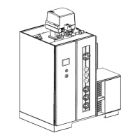
Clayton Steam Generator model EO-100-1M PAGE 1 / 70
Instruction Manual, doc.nr.: MAN18206 Rev A PSC
Order ref nr :
PR18206
INSTRUCTION MANUAL
STEAM GENERATOR
EO-100-1M
EUROPE, AFRICA & MIDDLE EAST HEADQUARTERS
CLAYTON OF BELGIUM NV
Rijksweg 30
B-2880 Bornem
Belgium
Tel.: +32-(0)3-8905700
Fax: +32-(0)3-8905701
E-mail: sales@clayton.be
www.clayton.be
CLAYTON DE FRANCE s.a.r.l. CLAYTON DEUTSCHLAND Gmbh
160, rue du Tuboeuf Lindemannstraβe 75
F-77170 Brie Comte Robert D-40237 Düsseldorf
France Germany
Tel.: +33-(0)1-64053824 Tel.: +49-(0)211-2339790
Fax: +33-(0)1-64052437 Fax: +49-(0)211-23397922
E-mail: lavapeur@clayton.fr E-mail: info@clayton-deutschland.de
www.clayton.fr www.clayton-deutschland.de
CLAYTON NEDERLAND B.V. p/a CLAYTON THERMAL PRODUCTS Ltd.
Rijksweg 30 5, Boleyn Court
B-2880 Bornem Manor Park Industrial Estate
Belgium Runcorn, Cheshire WA7 1SR, U.K.
Tel.: +31-(0)78-6139311 Tel.: +44-(0)1928-579009
Fax: +31-(0)78-6139347 Fax: +44-(0)1928-571155
E-mail: clayton@clayton.nl E-mail: sales@claytonindustries.co.uk
www.clayton.nl www.claytonindustries.co.uk

Table of Contents

Questions and Answers

  • B
    Brenda CuevasSep 12, 2025
    Why is the magnetic contactor noisy in my Clayton EO-100-1M Iron?
    • D
      Dominic PerkinsSep 12, 2025
      If the Clayton Iron's magnetic contactor is noisy, it may be due to poor alignment or mechanical binding. Disassemble and clean the magnetic contactor.
  • S
    susan29Aug 23, 2025
    Why is there smoke coming from the flue outlet of my Clayton Iron?
    • T
      Theresa HillAug 23, 2025
      If you notice smoke coming from the flue outlet of your Clayton Iron, it is crucial to address this immediately to prevent sooting of the heating coil and burner. Start by checking the air adjustment to ensure proper air supply to the burner. Also, adjust the fuel pressure as needed. Inspect the burner nozzle for carbon buildup, looseness, or wear; clean and tighten it, or replace it if it's worn. If the heating coil is sooted, attempt to remove it with a soot blower. Finally, ensure that the fuel is clean and of the correct grade, consulting the installation manual or specification table for details.
  • M
    millslisaAug 26, 2025
    What causes low fuel pressure in my Clayton EO-100-1M Iron and how do I fix it?
    • W
      whiteanneAug 27, 2025
      If the Clayton Iron's fuel pressure is too low, which requires stopping the generator immediately to prevent damage to the oil pump, start by checking the fuel level in the storage tank and ensuring that the supply lines aren't plugged. If the fuel pressure is not adjusted properly, adjust the fuel pressure regulator. Ensure the suction line is airtight and free of air pockets to prevent air leaks in the supply line that could cause pressure loss. If the fuel pump has failed, replace it.
  • G
    gillalisonAug 28, 2025
    What to do if the motor fails to start or stops during operation in my Clayton EO-100-1M Iron?
    • L
      Lori GarciaAug 28, 2025
      If the Clayton Iron's motor fails to start or stops during operation, it could be due to a power failure or thermic motor issue. Wait 2 to 3 minutes for the safety device to cool down, then reset it manually and restart the generator, looking for the underlying cause. Check if the motor is not overheated. Alternatively, a shutdown might be triggered by one of the safety devices; check which light is illuminated and correct the cause.
  • R
    Robert AndersonAug 29, 2025
    Why does the steam pressure discharge gauge reach zero pressure on my Clayton Iron?
    • T
      Todd MullinsAug 29, 2025
      If your Clayton Iron's steam pressure discharge gauge reads zero, this could be because the steam trap is closed, so ensure the waterpump is discharging at normal capacity. If not, the pressure gauge itself might be defective, and you should replace it.
  • T
    Todd ClarkAug 31, 2025
    Why is the flame dead or fluttering in my Clayton EO-100-1M Iron?
    • M
      Michael PattersonAug 31, 2025
      If you're experiencing a dead or fluttering flame in your Clayton Iron, it could be due to a restricted or sooted flue pipe, causing back pressure in the combustion chamber. Remove any soot or restrictions and ensure the flue pipe is installed correctly. The heating coil might also be sooted, so remove the soot with a sootblower. Ensure there's sufficient air to the boiler room, possibly by installing a duct from outside air to the blower. Check the air supply to the burner and adjust it properly. Finally, the burner nozzle might be carboned, so remove and clean it.
  • V
    Victoria HermanNov 23, 2025
    Why is the pump failing to maintain proper feed volume in my Clayton Iron?
    • M
      Michelle ReillyNov 23, 2025
      If the Clayton Iron's pump isn't maintaining the correct feed volume, causing thermostat interruptions, it could stem from several issues. Start by cleaning and inspecting the pump check valves to ensure they're functioning correctly. Insufficient level difference in the hotwell could also be a factor, so consult the installation manual for guidance. Ensure the waterpump is primed. Check for a leaking drain valve and close or replace it if necessary. Also, make sure the oil level in the waterpump is at the proper level to maintain pump capacity. If there are abrupt steam demands causing low pressure in the separator, consider installing a back pressure regulator to maintain normal pressure. Check that there is water at the waterpump inlet and that the water intake valve is open. Clean the ...
  • S
    Shelia FosterSep 13, 2025
    Why is the water pump noisy in my Clayton Iron?
    • R
      Robert SchmidtSep 13, 2025
      If you are experiencing noisy water pump operation in your Clayton Iron, it could be due to several reasons. The waterpump discharge snubber may not be working properly, so check and clean the intake surge chamber, and replace the rubber mould if necessary. A loose flexible coupling between the motor and pump can also cause noise, so tighten the setscrews in the flexible coupling. If the hotwell is not mounted at the proper height, install a boosterpump. Worn bearings or a lack of oil in the crankcase can also lead to noise, so replace the bearings if necessary and add oil to the proper level. Lastly, a restricted heating coil causing excessive back pressure can contribute to the noise, so check for scale formation in the heating coil by comparing the feed pressure with the normal value.
  • A
    Andrew AndrewsSep 10, 2025
    Why does the magnetic contactor fail to contact in my Clayton Iron?
    • C
      Charles WallaceSep 10, 2025
      If the Clayton Iron's magnetic contactor fails to contact, this could be due to operating coil failure, so replace the coil. Alternatively, contact failure might be caused by poor contact pressure, dirt, arcing, or low voltage, in which case you should replace the contactor.
  • T
    Teresa HillSep 7, 2025
    Why is oil dripping from the burner of my Clayton EO-100-1M?
    • J
      Jessica AlvaradoSep 7, 2025
      If you notice oil dripping from the burner of your Clayton Iron, it might be because the oil solenoid valve is not seating properly, so check and clean the oil solenoid valve. Alternatively, the burner nozzle could be loose, so tighten it. Carbon buildup on the burner nozzle can also cause deflection of the oil spray, so remove and clean the burner nozzle. Finally, poor setting of the ignition electrodes can contribute to this issue, so disassemble the burner and readjust the electrodes.

Summary

Safety Information

General Important Information

General safety warnings and precautions for operation, installation, and maintenance.

Installation

Safety directives for lifting, securing parts, and pipework installation.

Operation

Safety considerations during generator operation, including remote control.

Rest Risks

Identifies potential hazards during maintenance or operation.

General

General overview of risks like hot components, ventilation, and moving parts.

Pump

Hazards related to the pump, including hot surfaces and frost.

Coil and Steam; Water Separator

Risks associated with the coil and steam/water separator, including hot surfaces and water hammer.

Fuel and Air Piping

Hazards related to fuel and air piping, particularly in poorly ventilated areas.

Certification

Lists directives the steam generator complies with.

Description

General

General overview of the steam generator's capabilities and standard equipment.

Water and Steam System

Describes the flow and components of the water and steam system.

Flow

Details the path of water and steam through the system.

Waterpump

Describes the diaphragm type waterpump and its operation.

Steam Separator

Explains the function of the steam separator in separating steam and water.

Steam Trap

Describes the steam trap's role and operational checks.

Temperature Sensor

Explains the function of the temperature sensor and its role in shutdown.

Fuel System Oil Fired Units (Drawing HE-2673 )

Details the fuel delivery and burner operation for oil-fired units.

Automatic Burner Modulation

Explains how the burner modulates to maintain stable operation and efficiency.

Burner Manifold

Describes the burner manifold where fuel and air mix before ignition.

Electrical System & Main Components

Description of Main Components

Refers to electrical drawings for component descriptions and functions.

Operation

Explains the generator's operational sequence and control logic.

Generator On

Details the initial power-on sequence and alarm handling.

Burner On

Describes the process of starting the burner and its initial operation.

Burner Modulation

Explains how the burner modulates based on steam pressure.

Burner Stop at Maximum Steam Operating Pressure

Describes how the burner stops when maximum operating pressure is reached.

Alarm Stop

Lists various alarms that stop the generator and their causes.

Initial Firing

Before Firing

Procedures and checks to perform before initial startup for satisfactory operation.

Conditioning of New Installations or Installations with a New Coil

Steps for cleaning and preparing new installations or coils.

Purpose

Explains the objective of cleaning for new installations.

Step 1

The first step in conditioning new installations, involving flushing and chemical treatment.

Step 2

The second step in conditioning, involving a longer cleaning cycle.

Operation & Shutting Down

General

General guidelines for service personnel regarding operation.

Before Starting

Checks and valve positions required before starting the generator.

Starting Plant

Step-by-step procedure for starting the plant and priming the pump.

Starting the Burner

Procedure for igniting and starting the burner, including safety warnings.

Automatic Operation

How the generator operates automatically based on steam demand.

Shutting Down the Generator

Purpose and scope of shutting down the generator.

Dry Shut Down Procedure

Steps for a dry shutdown to conserve the generator and prevent freezing.

Wet Shut Down Procedure

Procedures for wet shutdown, considering feedwater tank installation.

If feedwater tank is installed at top level of installation

Specific wet shutdown procedures when the feedwater tank is at a high level.

If feedwater tank is not installed at top level of installation

Wet shutdown procedures when the feedwater tank is not at a high level.

Trouble Shooting

Water System

Troubleshooting common issues related to the water system.

Electrical System

Troubleshooting common problems with electrical components and motors.

Burner Failure

Diagnosing and resolving burner failures.

Periodic Maintenance

General

Importance of periodic inspection and maintenance for efficiency.

Feedwater Treatment

Importance of feedwater treatment for preventing corrosion and scale.

Daily Service

Routine daily checks and tasks for maintaining the generator.

Feedwater Control

Testing feedwater quality according to manual specifications.

Steam Pressure and Temperature

Recording pressure and temperature to detect coil restrictions.

Steam Trap Timing

Checking steam trap operation time for malfunctions.

Manual Blowdown

Procedure for manual blowdown to control dissolved solids.

Sootblow

Procedure for removing soot from the heating coil using steam.

Walk Around Inspection

Visual checks for leaks, noise, and smoke during operation.

Test of Burner Safety Controls

Testing the burner safety controls.

Weekly Maintenance

Maintenance tasks to be performed weekly.

Monthly Maintenance

Maintenance tasks to be performed monthly.

Feedwater Pressure at High Load

Checking feedwater pressure at high load for coil restriction.

Check Volute Pressure

Checking volute pressure to assess blower rotor condition.

Flushing Water Pumphead and Column

Flushing the water pump head and column.

Check Burner Safety Control

Testing burner safety control by simulating flame failure.

Draining and Cleaning of the Hotwell

Removing sludge from the hotwell.

Clean Blower Rotor

Cleaning dirt and lint from blower rotor blades for efficiency.

Clean and Adjust Burner

Cleaning and adjusting the burner components.

Service Annual (or Semi-Annual for Severe Service)

Annual or semi-annual service procedures, preferably by technician.

Periodic Inspection of Safety, Control and Monitoring Devices.

Periodic checks of safety, control, and monitoring devices for reliable operation.

Safety and Control Devices on the Steam Generator Assembly.

Overview of safety and control devices and their compliance with standards.

Component Maintenance

Feedwater Pump.J-2

Maintenance procedures for the feedwater pump.

Pump Check Valve Maintenance ( Fig 8.1 )

Maintenance of the pump's check valves.

Replacing Water Pump Valve Seats (Fig 8.2)

Procedure for replacing water pump valve seats.

Waterpump Diaphragm Replacement

Steps for removing and replacing the waterpump diaphragm.

Removal ( fig 8.1 )

Detailed steps for removing the diaphragm.

Reassembly ( fig 8.1 )

Steps for reassembling the waterpump after diaphragm replacement.

Waterpump Disassembly and Repair (Fig 8.1)

Procedures for disassembling and repairing the waterpump.

Disassembly

Steps for disassembling the waterpump.

Inspection

Inspection of pump components after disassembly.

Repair

Repair procedures for worn or damaged pump parts.

Reassembly

Steps for reassembling the waterpump.

Waterpump Oil Level Switch ( Fig 8.4)

Operation and adjustment of the waterpump oil level switch.

Waterpump Relief Valve (Fig 8.5)

Adjustment and repair of the waterpump relief valve.

Waterpump Intake Snubber

Information on the non-adjustable waterpump intake snubber.

Waterpump Discharge Snubber

Information on the non-adjustable waterpump discharge snubber.

Heating Coil

Description of the heating coil design and function.

Removal of Scale from Restricted Heating Coil (Fig 8.8)

Procedure for removing scale from a restricted heating coil.

Heating Coil Removal

Steps for removing the heating coil from the burner base.

Heating Coil Repair and Installation

Procedures for repairing and installing the heating coil.

Heating Coil Insulation

Procedures for insulating the heating coil.

Burner Base Insulation Replacement

Replacing the insulation in the burner base.

Burner Oil Fired Units & Fuel Pressure Regulator

Information on oil-fired units and the fuel pressure regulator.

Fuel Pressure Regulator

Details on adjusting the fuel pressure regulator for optimal performance.

Cleaning and Adjusting the Oil Burner Manifold

Cleaning and adjusting the oil burner manifold and nozzle.

Air Damper Adjustment E-100

How to adjust the air damper for optimal combustion.

Secondary Air Damper

Specifics on adjusting the secondary air damper.

Controller

Overview of the controller unit and its functions.

Start Generator.

Steps to start the generator and set low fire.

Start Burner.

Procedure for starting the burner and adjusting air/fuel mixture.

Configuration of Temperature Indicator JUMO ( 0202485 )

Steps to configure the JUMO temperature indicator settings.

Steam Pressure Switch (F20)

Adjustment of the steam pressure switch for burner control.

Modulation Pressure Switch [F22]

Adjustment of the modulating pressure switch for burner modulation.

Limit Pressure Switch [F21]

Adjustment of the limit pressure switch for safety.

Air Pressure Switch [ F81,-FIG 8.22 ]

Adjustment of the air pressure switch for burner operation.

Air Pressure Switch High Fire [F82 - FIG 8.22 ]

Adjustment of the high fire air pressure switch.

Recommended Oils for Clayton Waterpumps

Purpose and Scope.

Explains the purpose of selecting correct waterpump oils.

Oil Specifications

Lists specifications for recommended oils.

Oils for Food Industries

Specific oil recommendations for food industry applications.

Instruction and Operation for Pressure Vessels

Description of Pressure Vessel

Defines and describes pressure equipment used in the system.

Scope - Application.

Scope and application of the pressure vessel instructions.

Specifications. and Design Data

Refers to QC documents for specifications and design data.

Transport, Handling and Storage.

Guidelines for safe transport, handling, and storage of pressure equipment.

Assembling and Erection.

Procedures for assembling and erecting the pressure equipment.

Erection Conditions.

Conditions and safety measures for erecting pressure equipment.

Connecting and Preparing the Pressure Equipment.

Instructions for connecting and preparing the pressure equipment.

Safety and Pressure Accessories.

Installation of safety and pressure accessories.

Taking into Operation.

General instructions for taking pressure equipment into operation.

General Instructions.

General prerequisites and safety for initial operation.

Initial Start-up.

Procedure for initial cold start-up at minimum load.

Normal Operating Conditions.

Conditions for normal operation and the role of safety devices.

Putting out of Operation.

Procedures for safely taking the equipment out of operation.

Incorrect or Unexpected Use.

Actions to take if safe operation is endangered or parameters are exceeded.

Supervision and Maintenance.

General instructions for supervision and maintenance.

General Instructions.

Adhering to local stipulations for supervision and inspection.

Closing and Opening the Pressure Equipment.

Procedures for closing and opening pressure equipment openings.

Supervision and Inspection.

Guidelines for inspections by authorized personnel.

Inspection by Authorised Owner-Users.

Inspections performed by authorized owner-users.

In Service Inspection Program.

Requirements for in-service inspection programs.

Periodic Inspection of the Pressure Equipment.

Frequency and type of periodic inspection based on regulations.

Maintenance.

General maintenance requirements.

Maintenance

Safety precautions and general maintenance tasks for pressure equipment.

Pressure Equipment Repairs and Part Replacements.

Procedures and regulations for repairing pressure equipment and replacing parts.

Clayton EO-100-1M Specifications

General IconGeneral
BrandClayton
ModelEO-100-1M
CategoryIron
LanguageEnglish

Related product manuals