22
Terminals 7 & 8: Booster Pump -240VAC,60Hz,8AMP,1HP.Useminimum#14AWG.120VAC,60Hz,16AMP,use
minimum #12 AWG. Wire from the terminal strip to the booster pump as indicated. The booster pump will be controlled by the
interlockbox.Inmanycasesthisfeatureisnotbeused;theoperationoftheremainingequipmentwillnotbeaffected.
Terminals 9 & 10: Ozone Generator -240VAC,60Hz,2AMPor120VAC,60Hz,4AMP.Hardwiretheelectricalcordon
theozonegeneratortotheterminalstripasindicated.Theozonegeneratorwillbecontrolledbytheelectricalinterlockbox.
Air Dryer: 120VAC,60Hz,1AMP.Plugtheairdryerintoastandardwalloutlet120VAC,60Hz.Theairdryershouldremain
energizedatalltimeswiththeexceptionoflongtermshutdownforservice.Theairdryercanbehardwiredtotheelectrical
interlockboxutilizingterminals1(120V)and3(neutral).
Using a bonding wire conforming with all local, state and national electrical codes (normally a #8 AWG), ground the
components to the grounding bar on the electrical interlock box and bond the electrical interlock box to a true earth
ground.
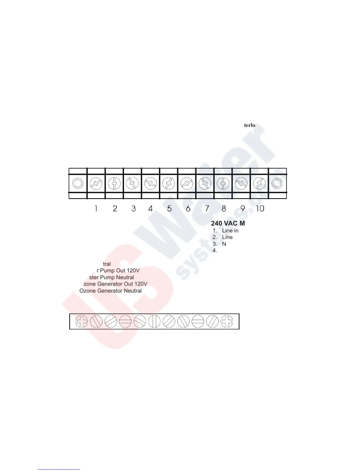
Electrical Connections - continued
120 VAC MODELS 240 VAC MODELS
1. Line in 120V 1. Line in 240V
2 Neutral in 2. Line in 240V
3. Neutral in 3. Neutral In
4. MCI in 4. MCI in
5. ORP Line in 5. ORP Line in
6. ORP Neutral 6. ORP Neutral
7. Booster Pump Out 120V 7. Booster Pump Line Out 240V
8. Booster Pump Neutral 8. Booster Pump Line OUt 240V
9. Ozone Generator Out 120V 9. Ozone Generator Out 240V
10. Ozone Generator Neutral 10. Ozone Generator Out 240V
Grounding Bar
 Loading...