CMS REMOTE ALARM Page 1
© 2019 CLEMCO INDUSTRIES CORP. www.clemcoindustries.com Manual No. 22978, Rev C, 06/19
1.0 INTRODUCTION
1.1 Scope of manual
1.1.1 These instructions cover set-up, operation, and
replacement parts for the CMS Remote Alarm.
1.1.2 This alarm is a potential life saving instrument. To
assure its performance it must be properly installed and
maintained. Before installing and using the alarm, all
personnel involved with the operation and maintenance
must read this manual and the applicable carbon
monoxide monitor manual noted below.
CMS-1 Carbon Monoxide Monitor .... Manual no. 23301
CMS-2 Carbon Monoxide Monitor .... Manual no. 22925
1.2 Safety Alerts
1.2.1 Clemco uses safety alert signal words, based on
ANSI Z535.4-2011, to alert the user of a potentially
hazardous situation that may be encountered while
operating this equipment. ANSI's definitions of the signal
words are as follows:
This is the safety alert symbol. It is
used to alert you to potential physical
injury hazards. Obey all safety
messages that follow this symbol to
avoid possible injury or death.
NOTICE
Notice indicates information that is considered
important, but not hazard-related, if not
avoided, could result in property damage.
CAUTION
Caution indicates a hazardous situation that, if
not avoided, could result in minor or moderate
injury.
WARNING
Warning indicates a hazardous situation that, if
not avoided, could result in death or serious
injury.
DANGER
Danger indicates a hazardous situation that, if
not avoided, will result in death or serious
injury.
1.3 Description
1.3.1 The 12 volt DC remote alarm is a high-intensity,
red-lens strobe light and high decibel horn. Use the
remote alarm in high noise areas or where the CO
monitor cannot be placed in a conspicuous location. The
alarm does not require an external power source when
correctly connected to a CMS monitor. The alarm
sounds and the strobe light flashes whenever the CO
monitor goes into an alarm condition. Using additional
cable, the alarm may be placed up to 150 ft. from the
monitor.
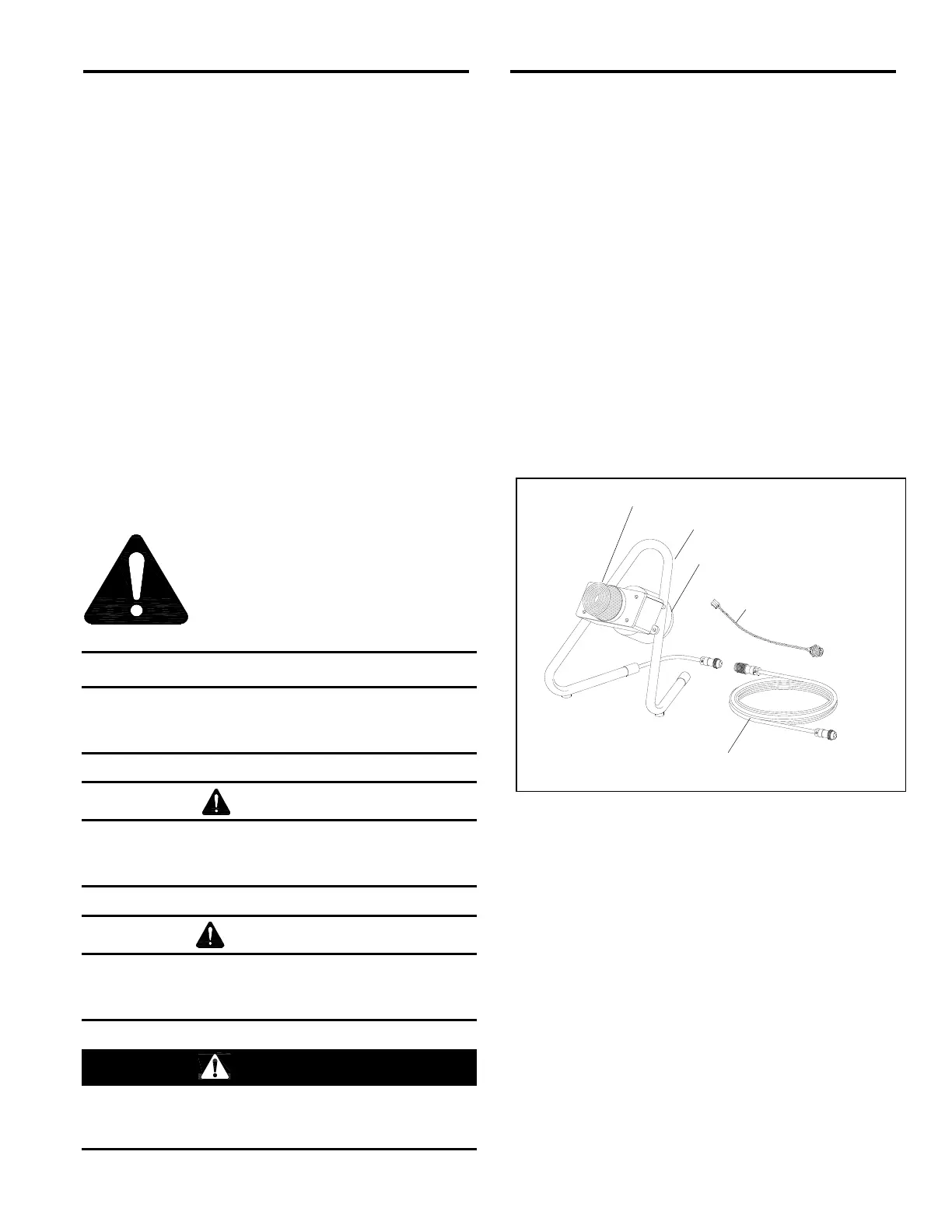
1.4 Components
1.4.1 The primary components of the remote alarm are
shown in Figure 1. The alarm package includes the
alarm case with strobe light and horn, stand, 50-ft. cable
with connectors, and a wire assembly with pin socket
and cable connector.
Figure 1
2.0 SET-UP
2.1 Disconnect all electrical power to the monitor.
2.2 Open the case to access the interior faceplate.
2.3 CMS-1: Remove the four screws and remove the
faceplate, being careful not to disconnect wires or
tubing.
CMS-2: Loosen the closing screw located in the
center of the lower edge of the faceplate and swing the
faceplate up to access the inside of the case.
2.4 Remove the plug from the hole located on the
bottom of the CMS-1 case, and on the right side of the
CMS-2 case. Ref. Figure 2 (CMS-2 is shown for
reference).
Horn
Stand w/ Pigtail
Alarm Wire Assembly
Strobe Light
50 Ft. Cable
w/ Connectors
 Loading...