CMS REMOTE ALARM Page 2
© 2019 CLEMCO INDUSTRIES CORP. www.clemcoindustries.com Manual No. 22978, Rev C, 06/19
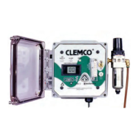
2.5 String the plug end of the alarm wire through the
case opening and slide the retaining nut onto the wire,
as shown in Figure 2. Push the cable connector firmly
into the case and tighten the retaining nut to secure.
Figure 2
2.6 Plug the alarm-wire socket onto the unused alarm
post (J3 or J4 on CMS-1) (J3 or J5 on CMS-2) located
on the circuit board, as shown in Figure 3.
Figure 3
3.0 Operation
3.1 The remote alarm does not require any special
mounting, and it will operate in any position. The stand
may be used free standing or used to hang the alarm in
a conspicuous place so any alarm condition will be
noticed.
WARNING
The remote alarm must be in a conspicuous
place to ensure that any alarm condition is
observed. DO NOT mount inside a blast room.
The alarm case and cable are not designed to
withstand the continual impact of abrasive that
takes place inside a blast room. For additional
external alarms, refer to the monitor manual for
instructions for installing external alarm
devices. With auxiliary terminals and a relay,
the monitor may be interlocked with other
devices, such as the compressor shut-down, to
additionally safeguard against an unobserved
alarm.
3.2 Place the alarm in a conspicuous location within
cable reach of the monitor. With additional cable, the
alarm may be place up to 150 ft. from the monitor.
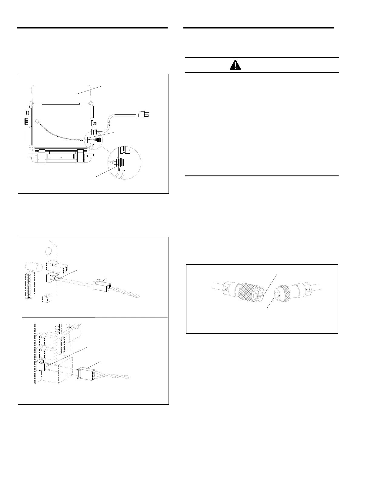
3.3 Connect cable to the monitor and the alarm:
Before connecting the cable connectors, make sure they
are correctly aligned by lining-up the locators of each
connector, as shown in Figure 4. Route the cable to
ensure that there will be no contact with ground traffic or
high reach equipment.
Figure 4
3.4 Refer to the monitor operations manual and test
the alarm using the same process for testing the
monitor’s internal alarms.
4.0 REPLACEMENT PARTS
Description Stock No.
Remote alarm kit, complete ................................... 22909
Strobe Light ............................................................ 22984
Horn ....................................................................... 22985
Wire assembly ....................................................... 22986
Cable with connectors, 50 ft. ................................. 22910
Stand assembly with pigtail ................................... 22987
Remove plug, and
string alarm wire
through opening.
Tighten retaining nut.
Swing faceplate up.
Locator Rise
Locator Channel
Align locators before connecting
Alarm-wire Socket
Alarm-wire Socket
Remote Alarm Post (J3 or J5)
CMS-1 Circuit Board
CMS-2 Circuit Board
Remote Alarm Post (J3 or J4)
 Loading...