Do you have a question about the Clevo W950TU and is the answer not in the manual?
Introduces the manual's scope, purpose, and the computer's upgradeability.
Lists detailed technical specifications for the notebook's components and features.
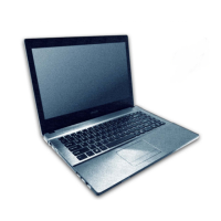
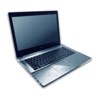
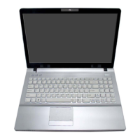
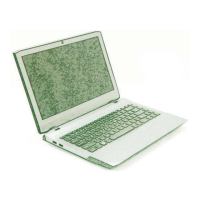
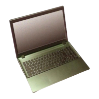
Identifies external components visible from the top view with the LCD panel open.
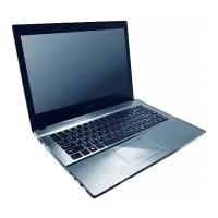
Identifies external components located on the front and right side views of the notebook.
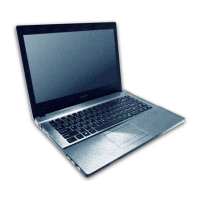
Identifies external components on the left side and rear views of the notebook.
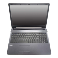
Identifies external components visible on the bottom view of the notebook.
Highlights key components on the top side of the mainboard.
Highlights key components on the bottom side of the mainboard.
Identifies and locates connectors on the top side of the mainboard.
Identifies and locates connectors on the bottom side of the mainboard.
Introduces the chapter on disassembling notebook parts and subsystems.
Lists recommended tools for performing maintenance and disassembly procedures.
Describes the four types of connections found within the computer.
Provides crucial precautions for personal safety and preventing computer damage during service.
Lists disassembly steps and corresponding page numbers for finding related information.
Provides step-by-step instructions for safely removing the computer's battery.
Details the process for removing and upgrading the notebook's hard disk drive.
Provides step-by-step instructions for removing the optical drive.
Details the procedure for removing the hard disk caddy or second hard disk.
Explains how to remove and replace the system memory modules (RAM).
Provides instructions for safely removing the notebook's keyboard.
Details the process for removing the Wireless LAN module.
Describes cable identification for WLAN and Bluetooth combo modules based on color coding.
Provides steps for removing the CCD (Camera) module from the notebook.
Provides a table indicating where to find specific part list illustrations.
Lists parts associated with the top view of the notebook with one DIMM slot.
Lists parts associated with the top view of the notebook with two DIMM slots.
Lists parts associated with the bottom view of the notebook.
Lists parts related to the notebook's LCD screen assembly.
Lists parts for the DVD Dual drive component of the notebook.
Lists parts associated with the Hard Disk Drive (HDD) component.
Lists parts related to the HDD Caddy assembly.
Provides a high-level block diagram of the notebook's system architecture.
Presents the first part of the processor schematic diagrams.
Presents the second part of the processor schematic diagrams.
Presents the third part of the processor schematic diagrams.
Presents the fourth part of the processor schematic diagrams.
Presents the fifth part of the processor schematic diagrams.
Presents the sixth part of the processor schematic diagrams.
Presents the seventh part of the processor schematic diagrams.
Presents the eighth part of the processor schematic diagrams.
Shows the schematic diagram for the first DDR3 SO-DIMM slot.
Shows the schematic diagram for the second DDR3 SO-DIMM slot.
Presents the schematic diagram for the RTD2136 component.
Shows the schematic diagram for the panel connector and CRT port.
Presents the schematic diagram for the HDMI connector and related circuitry.
Shows the schematic diagram for the LAN and Card Reader components.
Presents the schematic diagram for the Mini Card slot and associated circuitry.
Shows schematic diagrams for HDD, ODD, LED indicators, and LID switch.
Presents schematic diagrams for USB ports and the touch panel interface.
Shows schematic diagrams for various connectors and components like CCD, Fan, Click, TV.
Presents the schematic diagram for the Audio Codec component.
Shows the schematic diagram for the Keyboard Controller (KBC) IT8587E.
Presents the schematic diagram for the AU6259 USB Hub controller.
Shows schematic diagrams for various voltage regulators.
Presents schematic diagrams for the VDD3 and VDD5 power rails.
Shows schematic diagrams for 1.5VS, 1.5V, and VTT_MEM voltage regulators.
Presents schematic diagrams for 1.0V, 1.05VS, and 1.24V voltage regulators.
Shows the schematic diagram for the VCore voltage supply.
Presents the schematic diagram for the AC input and battery charging circuit.
Shows the schematic diagram for the separate Audio Board.
Presents the schematic diagram for the Trusted Platform Module (TPM).
Shows the schematic diagram for the Switch (SW) Board, including power and LEDs.
Presents the schematic diagram for the Touch Panel Transfer Board.
Shows the schematic diagram for the first level shifter circuit.
Presents the schematic diagram for the second level shifter circuit.
Lists the essential steps required to successfully update the computer's BIOS.
Guides users on how to download the correct BIOS files from the manufacturer's website.
Instructs on preparing the downloaded BIOS files onto a bootable media.
Explains how to configure the computer's BIOS to boot from an external drive.
Details the commands and process for using flash tools to update the BIOS.
Guides on restarting the computer and configuring BIOS settings after the update.