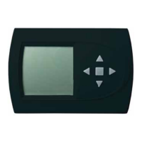
ACDU03 Communicating Service Tool
Rev.: November 3, 2017
6
Geothermal Heat Pump Systems
VARIABLE SPD INTERNAL
PUMP CONFIGURATION
LOOP OPTION SINGLE
PUMP CONTROL FIXED
HEATING STAGE 1 60%
COOLING STAGE 2 75%
COOLING STAGE 1 50%
COOLING STAGE 2 70%
PREVIOUS SELECT
3.4 PUMP CONFIGURATION
vFlow™ vs internal fl ow control pump can be controlled either
through temperature differential (Delta T) or can be set to
specifi c speed (fi xed; % of full speed for each heat and cool
stage).
Can be confi gured for either single pumping or parallel
pumping.
Confi gure temperature differentials at the thermostat for
vFlow™ units with an internal fl ow control pump.
Adjust the Pump Confi guration settings using the up/down
arrow buttons. Press the center button to select each item.
• Heating Delta T (default stored in control) –
valid range: 4 to 12ºF (in 1ºF increments)
• Cooling Delta T (default stored in control) –
valid range: 9 to 20ºF (in 1ºF increments)
Maximum Heat LWT (valid range based on specifi c model;
refer to model IOM). Minimum Cool LWT (valid range based
on specifi c model; refer to model IOM).
NOTE: Refer to section 3.6.3 for multi-unit confi guration
instructions.
To control vs pump by fi xed speed, select ‘Pump Control’,
press , use down arrow to select ‘Fixed’, and press to
save.
Default stored in control. Valid range: 15% - 90% (in 1%
increments)
Heating Stage 1 Cooling Stage 1
Heating Stage 2 Cooling Stage 2
If Pump Confi guration is set to ‘VS PUMP PARALLEL’, valid
range changes to 50-90% (in 1% increments).
3.5 VALVE CONFIGURATION
Confi gure temperature differentials at the thermostat for
vFlow™ units with a motorized modulating valve.
Adjust the Valve Confi guration settings using the up/down
arrow buttons. Press the center button to select each item.
• Heating Delta T (default stored in control) –
valid range: 4 to 12ºF (in 1ºF increments)
• Cooling Delta T (default stored in control) –
valid range: 9 to 20ºF (in 1ºF increments)
NOTE 1: Minimum and Maximum degree values are shown
only when the control is confi gured with the appropriate
values.
NOTE 2: Refer to section 3.6.3 for multi-unit confi guration
instructions.
3.5.1 MODULATING VALVE OFF POSITION
For certain commercial multi-unit applications, the modulating
valve can be kept slightly open by choosing values 3.3-4.0.
MODULATING VALVE
CONFIGURATION
OFF POSITION 0.0
VALVE CONTROL DELTA T
HEATING DELTA T 7 F
COOLING DELTA T 10 F
MAXIMUM HEAT LWT 80 F
MINIMUM COOL LWT 40 F
PREVIOUS SELECT
VARIABLE SPD INTERNAL
PUMP CONFIGURATION
LOOP OPTION PARALLEL
PUMP CONTROL DELTA T
HEATING DELTA T 7 F
COOLING DELTA T 10 F
MAXIMUM HEAT LWT 80 F
MINIMUM COOL LWT 40 F
PREVIOUS SELECT


 To Next Page
 Loading...