0RQWDĪLQVWDODFMDHOHNWU\F]QDLXUXFKRPLHQLH/Installation, electrical connections and start-up
2.10RQWDĪNOLPDNRQZHNWRUD
.OLPDNRQZHNWRUPXVLE\üPRQWRZDQ\GRNáDGQLHZSR]LRPLHRUD]ZSR]\FML
XPRĪOLZLDMąFHMáDWZ\GRVWĊSGRXU]ąG]HQLD]DUyZQRZFHOXUXW\QRZHM
NRQVHUZDFMLF]\V]F]HQLHILOWUDMDNUyZQLHĪZFHOXSU]HSURZDG]HQLD
V]F]HJyOQ\FKF]\QQRĞFLVHUZLVRZ\FK
:FHOX]DPRQWRZDQLDNOLPDNRQZHNWRUDSRVWĊSXMZQDVWĊSXMąF\VSRVyE
• =GHMPLMREXGRZĊSROX]RZXMąFĞUXE\PRFXMąFH)LJ$
• -HĪHOLGRXU]ąG]HQLDGRáąF]RQRQyĪNLQDOHĪ\]DPRQWRZDüMH]JRGQLH-
]GRáąF]RQąGRQLFKLQVWUXNFMą
• 3U]\PRFXMPRGXáZHQW\ODWRUDGRĞFLDQ\OXEVXILWXXĪ\ZDMąFNRáNyZ
UR]SRURZ\FK)LJ%PRQWDĪZSLRQLH)LJ&PRQWDĪZSR]LRPLH
• =DOHFDQHMHVWSRGáąF]HQLHZORWXZRG\GRGROQHJRSU]\áąF]D3RGáąF]
UXUNLQDGRSá\ZLHGRZ\PLHQQLNDRUD]]DLQVWDOXMRGSá\ZVNURSOLQ
• 3U]HZRG\GRSURZDG]DMąFHZRGĊPXV]ą]RVWDüRGSRZLHGQLR]DL]RORZD
QHDE\XQLNQąüNáRSRWOLZHMNRQGHQVDFMLWZRU]ąFHMVLĊZF]DVLHSUDF\Z
WU\ELHFKáRG]HQLD
• 'R]ELHUDQLDZRG\WZRU]ąFHMVLĊQDSRáąF]HQLDFKLQVWDODFMLZRGQHMVWR
VXMHVLĊVSHFMDOQąRSFMRQDOQąWDFĊRFLHNRZą
• 2GSá\ZVNURSOLQPXVLE\üSUDZLGáRZR]Z\PLDURZDQ\DQDFDáHMGáX
JRĞFLUXUQDOHĪ\SU]HZLG]LHüQDFK\OHQLHXPRĪOLZLDMąFHSUDZLGáRZHRG
SURZDG]HQLHVNURSOLQ
• -HĪHOLVNURSOLQ\RGSURZDG]DQHVąGRNDQDOL]DFMLNRQLHF]QHMHVW]DVWR
VRZDQLHV\IRQX]DSRELHJDMąFHJRSU]HGRVWDZDQLXVLĊQLHSU]\MHPQ\FK
]DSDFKyZGRSRPLHV]F]HQLD)LJ(
• =DPRFXMREXGRZĊNRU]\VWDMąF]HĞUXEPRFXMąF\FK
8ZDJD
3RGF]DVSRGáąF]DQLDSU]HZRGyZ]DZV]HWU]\PDMSU]\áąF]HZ\
PLHQQLND]DSRPRFąNOXF]DDE\XQLNQąüMHJRXV]NRG]HQLD)LJ'
8ZDJD
=DOHFDP\PRQWRZDQLHNOLPDNRQZHNWRUDQDZ\VRNRĞFLQLHSU]HNUDF]D
MąFHMPHWUyZ
2.1 Installation of the fan coil unit
The fan coil unit must be installed in a perfectly horizontal position and
in a position that allows easy access for both routine maintenance (filter
cleaning) as well as special maintenance.
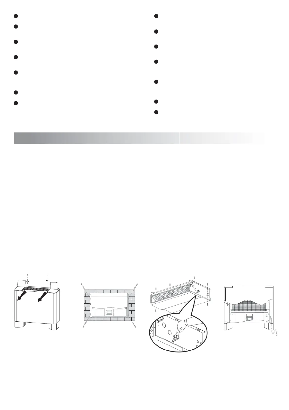
To install the fan coil unit proceed in the following manner:
• Remove the enclosure by loosening the fastening screws (Fig. A).
• If feet are included they must be mounted in accordance with the
instructions provided with them.
• Fasten the fan group to the wall or to the ceiling with the expansion
screws (Fig. B vertical, Fig. C horizontal).
• It is advisable to connect the water inlet to the lower coupling.
Connect the pipes for the supply of the coil and connect the conden -
sation discharge.
• The water supply pipes must be adequately insulated to avoid bother -
some dripping during cooling operation.
• To collect the water that forms on the water connections, a special
condensation collection tub is used (optional).
• The discharge of the condensation must be properly sized, and the
pipes must include over their entire length an inclination that allows for
proper drainage of condensation.
•
If the condensation drain flows into the sewer system, it is necessary to
realize a trap that prevents bad odors form entering the room
(Fig. E).
•
Fix the enclosure by the fastening screws
.
Attention!
During connection of the pipes, always hold the coil coupling with
a wrench to avoid damaging it. (Fig. D).
Note
We suggest installing the fan coil unit at a height not greater than 3
meters.
)LJ$
)LJ%
)LJ&
)LJ'
)LJ(
Enclosure
This is realized in pre-painted, rust and corrosion resistant sheet
metal.
Air filter
Washable dry air filter in acrylic material, placed in a sturdy galvanized
sheet metal frame.
Internal frame
Built in thick galvanized sheet metal with pre-punched holes for the
various configurations.
Condensation discharge
This makes it possible to discharge the condensation even in special
conditions, due to the particular capacity of the tray and substantial
diameter of the discharge pipe.
Water connections
The water connections are normally found on the rh side of the fan coil
unit, on the lh side if the heat excange coil is field rotated, and they
measure 1/2” G for all models.
Heat exchange coil
Copper pipes and carved aluminium ¿QQV
Air bleed valves
These are found on the water connections of the coil and make it pos -
sible to bleed air from the coil.
7
8
9
2EXGRZD
:\NRQDQD]ZVWĊSQLHPDORZDQHMEODFK\QLHUG]HZQHM
)LOWUSRZLHWU]D
6XFK\]P\ZDOQ\ILOWUSRZLHWU]DZ\NRQDQ\]WNDQLQ\DNU\ORZHM]DPRFR
ZDQ\QDUDPLH]EODFK\JDOZDQL]RZDQHM
5DPDZHZQĊWU]QD
:\NRQDQD]FLHQNLHMEODFK\JDOZDQL]RZDQHM]ZVWĊSQLHZ\ELW\PLRWZR
UDPLGODUyĪQ\FKNRQILJXUDFML
2GSá\ZVNURSOLQ
8PRĪOLZLDRGSURZDG]HQLHVNURSOLQQDZHWZZ\MąWNRZ\FKV\WXDFMDFK
G]LĊNLRNUHĞORQHMSRMHPQRĞFLWDF\RFLHNRZHMLGXĪHMĞUHGQLF\UXUNLVNURSOLQ
3U]\áąF]DZRGQH
3U]\áąF]DZRGQHVWDQGDUGRZR]QDMGXMąVLĊ]SUDZHMVWURQ\NOLPDNRQZHN
WRUDOXE]OHZHMVWURQ\ZSU]\SDGNXREUDFDQLDZ\PLHQQLNDFLHSáDQD
PLHMVFXPRQWDĪXĝUHGQLFDSU]\áąF]\GODZV]\VWNLFKPRGHOLZ\QRVL*
:\PLHQQLNFLHSáD
:\NRQDQ\]UXUPLHG]LDQ\FKLSURILORZDQ\FKODPHOLDOXPLQLRZ\FK
=DZRU\RGSRZLHWU]DMąFH
=QDMGXMąVLĊSRVWURQLHSU]\áąF]\ZRGQ\FKLXPRĪOLZLDMąRGSRZLHWU]HQLH
Z\PLHQQLND
4
5
6
7
8
9
4
5
6
 Loading...