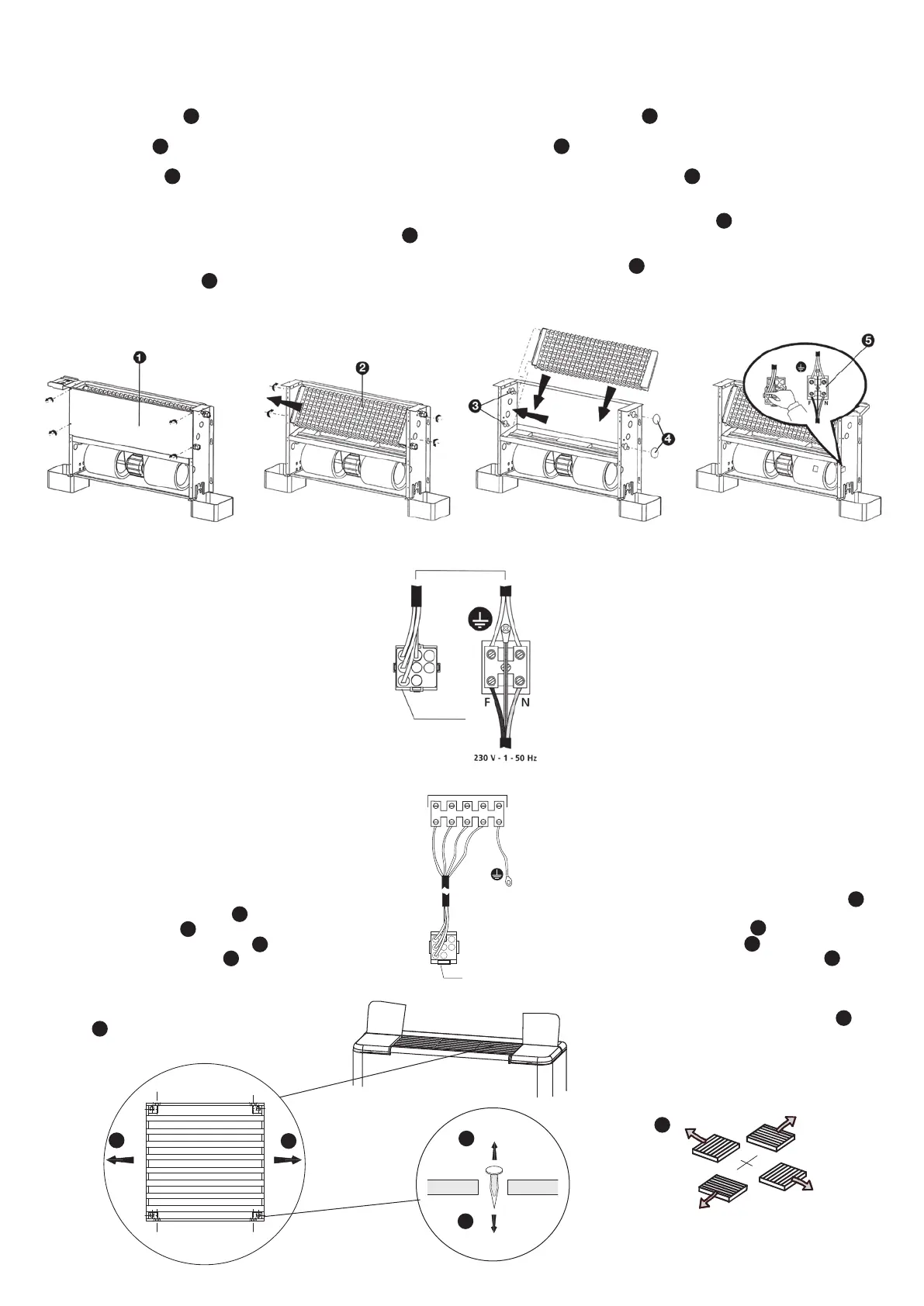
2.2 Coil rotation
If installation requirements make it necessary to rotate the coil, proceed
in the following manner:
• Remove the cabinet from the fan coil unit (Fig. A).
• Remove protection panel 1 located in front of the coil by loosening
the relative screws.
• Slide coil 2 stniop gninetsaf eht no gnitca retfa tinu naf eht morf tuo
(Fig. B).
• Remove the pre-punched pieces 3 from the lf side (Fig. C).
• Insert the coil after rotating it and then fasten it.
• Close the holes of the water connections which are unused on the rh
side with the included adhesive rubber 4 .
• Move the control support with its wiring to the rh side of the fan coil
unit (Fig. D).
• Move earth connection 5 to the rh side.
• When the operation is concluded re-install the cabinet.
2.2 Obracanie wymiennika
Jeżeli montaż wymaga obrócenia wymiennika, postępuj zgodnie z poniż-
szym opisem:
• Zdemontuj obudowę klimakonwektora (Fig. A).
• Zdejmij panel ochronny znajdujący się przed wymiennikiem, polu-1
zowując odpowiednie śruby.
• Wysuń wymiennik z modułu wentylatora po poluzowaniu odpowied- 2
nich mocowań (Rys. B).
• Usuń kawałki blachy z wstępnie naciętych otworów po lewej stronie
(Fig. C).
3
• Obróć wymiennik, wsuń go na miejsce i przymocuj.
• Zaślep otwory po niewykorzystanych przyłączach wodnych po prawej
stronie, korzystając z dołączonej, przylegającej taśmy gumowej .4
• Przesuń podstawkę układu sterowania wraz z jej okablowaniem na
prawą stronę klimakonwektora (Fig. D).
• Przesuń złącze uziemienia na prawą stronę.5
• Po wykonaniu tych czynności, ponownie zamontuj obudowę.
Fig. D
Fig. A
Fig. B
Fig. C
2.3 Electrical connections
Before carrying out any operations on the el ectri-
cal part of the fan coil unit, disconnect the ele -
ctrical mains power supply by turning off the main
switch. Always remember to connect the earth
wire. The earth connection is required by law.
The installer must provide for its realization by using
the appropriate terminal which is marked with the
international symbol for earth connections.
The electrical connections must be made as
shown in the picture E and picture F.
2.4 Start-up
Bleed the system after having filled it.
Also bleed the fan coil unit by means of the
appropriate valves and check fan coil unit for
proper operation.
Attention!
The first start-up of the fan coil unit must be
made at maximum speed, letting the fan run
for 4-5 hours. Repeat this operation after a
long shutdown period.
2.5 Grilles orienting
• Free the extreme right grille lifting the pins
(Fig. G);
• Shift grilles to the right and remove them;
• Turn grilles as desired ;
• Insert grilles and shift them to the left ;
• Block the last grille on the right punching the
precut hole of the cabinet or putting in cor -
respondence the space between the last two
finns with the hole and reinsert the pins .
Wbudowany system sterowania (wersja pionowa)
Built-in to control (vertical versions)
Złącze
Connector
Fig. E
Fig. G
2.3 Instalacja elektryczna
Przed rozpoczęciem jakichkolwiek prac związanych
z instalacją elektryczną klimakonwektora, odłącz
urządzenie od źródła zasilania, przełączając główny
wyłącznik. Zawsze pamiętaj o podłączeniu przewodu
uziemiającego. Uziemienie jest wymagane prawnie.
Do tego celu instalator powinien wykorzystać odpo-
wiedni zacisk oznaczony międzynarodowym sym-
bolem określającym miejsce podłączenia uziemienia.
Instalację elektryczną należy wykonać zgodnie z ry-
sunkami E i F.
2.4 Uruchomienie
Po napełnieniu układu, odpowietrz go.
Należy również odpowietrzyć klimakonwektor, ko-
rzystając z właściwych zaworów oraz sprawdzić
poprawność jego działania.
Uwaga!
Pierwsze uruchomienie klimakonwektora na-
leży wykonać przy maksymalnych obrotach,
umożliwiając pracę wentylatora przez 4-5 go-
dzin. Powtórz tę czynność po dłuższych przer-
wach w pracy.
2.5 Kierunek montażu kratek
•
Wyjmij kratkę znajdującą się najbardziej z prawej
strony, wyciągając w górę szpilki (Fig. G);
• Przesuń kratki w prawo i zdemontuj je;
• Ustaw kratki zgodnie z wymaganiami ;
• Wsuń kratki i przesuń je w lewo ;
•
Zablokuj ostatnią kratkę po prawej stronie, wybi-
jając wstępnie nacięty otwór w obudowie lub do-
pasowując przestrzeń między dwoma ostatnimi
prowadnicami i otworem, zamontuj ponownie
szpilki .
1
2
3
4
5
3
1
5
2
4
1
2
3
4
5
Fig. F
Zdalne sterowanie (wersja pozioma)
Remote control (horizontal versions)
Złącze / Connector
 Loading...