EasyManua.ls Logo

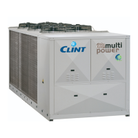
Clint MultiPower CHA/K 18012-P

Clint MultiPower CHA/K 18012-P
36 pages
To Next Page IconTo Next Page
Loading...
R410A
REFRIGERATORI D’ACQUA
ARIA/ACQUA FREE-COOLING
CON VENTILATORI ASSIALI E
COMPRESSORI SCROLL
DA 208 kW A 1102 kW
WATER CHILLERS
FREE-COOLING
WITH AXIAL FANS AND
SCROLL COMPRESSORS
FROM 208 kW TO 1102 kW
GROUPES D’EAU GLACÉE
FREE-COOLING AVEC
VENTILATEURS AXIAUX ET
COMPRESSEURS SCROLL
DE 208 kW À 1102 kW
FLÜSSIGKEITSKÜHLER
FREIE KÜHLUNG
MIT AXIALLÜFTERN UND
SCROLL VERDICHTERN
VON 208 kW BIS 1102 kW
Serie / Series / Serie / Série
CHA/K/FC 726-P÷36012-P
Emissione / Issue
Ausgabe / Edition
Sostituisce / Supersedes
Ersetzt / Remplace
02.11 ---
Catalogo / Catalogue / Katalog / Brochure
CLB 48.7

Table of Contents

Question and Answer IconNeed help?

Do you have a question about the Clint MultiPower CHA/K 18012-P and is the answer not in the manual?

Clint MultiPower CHA/K 18012-P Specifications

General IconGeneral
BrandClint
ModelMultiPower CHA/K 18012-P
CategoryChiller
LanguageEnglish

Summary

General Description

Energy Saving

Operating Principle

General Technical Data

Refrigerant Cycle Data

Provides key performance metrics for the refrigerant cycle.

Free-Cooling Cycle Data

Details performance metrics specifically for the free-cooling function.

Water Circuit Data

Specifies water flow rates, pressure drops, and connections.

Refrigerating Efficiencies

Water Circuit Pressure Drops

Refrigeration Circuit Diagram

Water Circuit

Water Circuit Diagram

Provides a schematic diagram of the unit's water circuit and its components.

Units with Pumps

Characteristic Pump Curves

Dimensions and Clearances

Microprocessor Control System

Principal Functions

Details the main functions and capabilities of the unit's microprocessor controller.

Alarms

Lists the types of alarms and error conditions managed by the control system.

Wiring Diagrams Explanation

Power Electrical Diagram

Control Electrical Diagram

Installation Recommendations

Electrical connections

Details the necessary steps and precautions for making electrical connections.

Hydraulic connections

Outlines the procedure for connecting the unit to the hydraulic system.

Start up and maintenance operations

Offers recommendations for initial unit startup and ongoing maintenance procedures.

Related product manuals