EasyManua.ls Logo

Clinton Electronics CE-M21A-PIR User Manual

Clinton Electronics CE-M21A-PIR
7 pages
To Next Page IconTo Next Page
Page #1 background imageLoading...
Page #1 background image
1
Information in this document is subject to change without notice.Basic Setup Guide: CE-M21A-PIR / CE-M27A-PIR / CE-M32A-PIR
02.08.19
CE-M21A-PIR / CE-M27A-PIR / CE-M32A-PIR
24V POWER SUPPLY REQUIRED. SOLD SEPARATELY
Basic Setup Guide: 21”, 27” & 32” IP PVMs with Axis M3045 Camera
HDMI ALARM
ANALOG
OUTPUT
LAN
DC24V
AUTO
MENU
UP
DOWNPOWER
Remove Cover Plate and Install PVM:
Remove the cover plate on the back-side of the PVM
and set aside. Install the PVM to desired VESA mounting
bracket following instructions supplied with the mount.
*Mounting Bracket Not Included, Sold Separately.
1
Connect DC24V Power:
Connect DC24V power to PVM (using the supplied
pigtail adapter cable) or AC110V (32” models only). It is
recommended that the power supply not be plugged into
the main power source during this step *Power Supply
Not Included, Sold Separately.
2
Connect Network:
Connect an ethernet cable to the port marked LAN.
To view the IP camera on the network follow the setup
instructions from the included IP camera software. This
device does not support PoE connection.
3
Turn Power ON:
After making the power and network connections, plug the power supply into a wall outlet. Connecting the
DC24V pigtail into the PVM while plugged into the main power source can cause sparking.
4
Camera Boot-Up:
Colored bars will display on the screen while the Axis IP camera is booting up. These bars will be on the screen
for approximately 20-30 seconds.
5
DC24V Ethernet
VESA Mounting HolesCamera Access Door
Camera Angle Adjustment:
If the camera appears to be slightly rotated the
angle might need to be adjusted. To adjust remove the 2
screws on the camera access door. Then turn the front of
the camera left/right until straight. Align the notch on the
front of the camera to the notch on the camera housing.
6
Align 2 Notches
Front Notch
Housing Notch
This is not a PoE device.
This device does not support WiFi
32” models: DO NOT CONNECT DC24V & AC110V POWER SIMULTANEOUSLY. Connecting both will cause
damage to the device.
Question and Answer IconNeed help?

Do you have a question about the Clinton Electronics CE-M21A-PIR and is the answer not in the manual?

Clinton Electronics CE-M21A-PIR Specifications

General IconGeneral
BrandClinton Electronics
ModelCE-M21A-PIR
CategoryMonitor
LanguageEnglish

Summary

Basic Setup Guide

Remove Cover Plate and Install PVM

Procedure to remove the cover plate and install the PVM to a VESA mounting bracket.

Connect DC24V Power

Connecting the DC24V power to the PVM using the supplied pigtail adapter cable or AC110V.

Connect Network

Connecting an Ethernet cable to the LAN port for network view.

Turn Power ON

Plugging the power supply into a wall outlet after connections are made.

Camera Boot-Up

Observation of colored bars on screen during camera boot-up for 20-30 seconds.

Camera Angle Adjustment

Adjusting camera angle by removing screws and turning the camera left/right.

Display Image Modes

Camera Mode

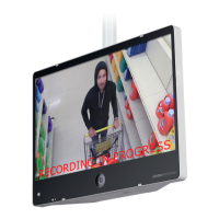
Only the camera image is shown on the screen of the PVM, no switching occurs.

HDMI Mode

Only a connected HDMI input is shown on the screen of the PVM, no switching occurs.

SD Video Mode

Only content from the SD Card player is shown on the screen, no switching occurs.

Motion Mode

Screen switches to camera image when PIR sensor detects motion; otherwise shows SD Card content.

Display Image Modes Continued

Switch HDMI Mode

Screen switches between HDMI input and camera image at set time intervals.

Switch SD Video Mode

Screen switches between camera image and SD Card content at set time intervals.

Camera VOV Switch Mode

Displays SD Card content in corner over camera image at set intervals.

Motion VOV Mode

Camera image is full screen; PIR sensor triggers SD Card content overlay.

Alarm VOV Mode

SD Card content full screen until alarm triggers 'Return to Cashier' message.

Alarm Mode

Camera image until alarm triggers 'Return to Cashier' message.

System Settings Message and LED Control

On/Off Setting

Turns the text overlay message ON or OFF.

Message Setting

Selects a text overlay message from predefined options.

Message Position Setting

Sets the message position to the TOP or BOTTOM of the screen.

Message Flash Setting

Sets the flashing interval for the message display.

LED Control Setting

Turns the flashing LED on the front of the PVM ON or OFF.

Please Return to Cashier Setting

Sets duration for the 'Please Return to Cashier' message display.

Formatting Image for SD Card

Format SD Card

Steps to format an SD card to FAT32 using a Windows PC.

Create/Modify Image

Resizing or creating images to 1024x768 pixels using editing software.

Save Image to SD Card

Saving the resized image as JPG, BMP, or PNG to the SD Card.

Resetting the AXIS M3045 Camera

Disconnect Power

Disconnecting power from the PVM before proceeding with the reset.

Access Camera and Remove Screws

Removing two door screws to access the camera for reset.

Press and Hold Control Button

Pressing and holding the control button while reconnecting power.

Continue Holding Button

Holding the control button until the LED flashes Green/Red for reset.

Resetting the AXIS M3045 Camera Continued

Set Capture Mode

Setting the Capture Mode to 1080p (HDMI) for camera image display.

Mirror Output Image

Toggling the 'Mirror Output Image' setting to OFF for legible display.

Related product manuals