92
M0CZ00007-03
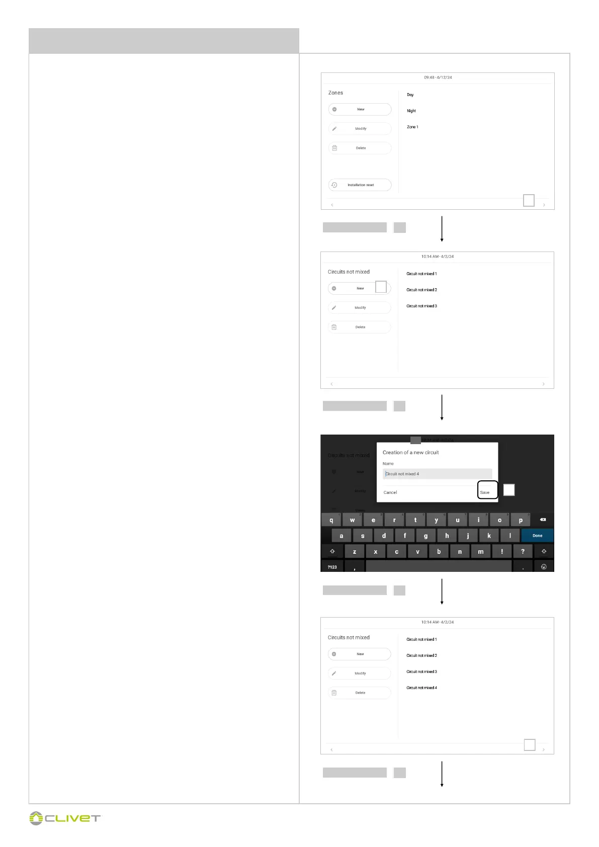
SYSTEM COMPONENT CONFIGURATION
select
9
select
10
select
11
select
12
Define the hydraulic circuits:
high temperature non-mixed circuits (max. 10)
Circuits greater than 4 refer to the 1st high temperature area
low temperature mixed circuits (max. 3) refer to the
subsequent page
Possible combinations with boosters:
STD booster
area 1: high temperature only
optional boosters
2 areas: high temperature only
2 areas: one high temperature + one low temperature
3 areas: high temperature only
3 areas: two high temperature + one low temperature
3 areas: one high temperature + two low temperature
4 areas: high temperature only
4 areas: three high temperature + one low temperature
4 areas: two high temperature + two low temperature
4 areas: one high temperature + three low temperature
9
12
10
11
 Loading...