Do you have a question about the CLIVET MSAT-XEE 22.2 and is the answer not in the manual?
The unit has been designed and created to prevent injuries to people. Reports residual risks.
Plan periodic inspection and maintenance to avoid or reduce repairing costs.
Disable unit immediately, contact certified service agent, use original spares.
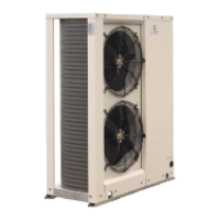
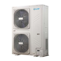
Units are designed for EXTERNAL, fixed positions. Limit vibration transmission.
Aware of refrigerant traps in closed zones. Temperature increase can cause explosion.
Recommended for longer pipes (>10m) or variable climatic conditions. Position near evaporating unit.
Check taps, pressurize with nitrogen, spray for leaks, discharge nitrogen.
Ensure service outlets are closed. Vacuum pump connection and operation.
Check refrigerant type on label. Charge must be completed during start-up.
Refer to electrical diagram, verify supply, ensure isolation, correct earth connection, protect cables.
Diagram of connections for unit, fuses, isolating switch, electrical panel, customer connections.
Operations done by qualified technician. Electrical/water connections by installer. Agree start-up data.
Unit OFF power supply checks: safety access, functional spaces, refrigerant lines, vacuum, air flow, etc.
Unit ON power supply sequence: voltage measure, compressor heaters, phase check, shut-off valve, unit ON.
Correct compressor rotation direction. Detect operational parameters: discharge temp, pressure, liquid temp, return pressure.
Verify ground connection, conductor tightening, voltage, frequency, and phase balance.
Connect oil resistances 8 hours before start-up. Ensure heaters are working, check temperature.
Check air/water temps, voltage, total absorption, and absorption of single electric loads.
Identify operating conditions: voltages, absorptions, temperatures, flows, refrigerant circuit parameters.
Navigation through modes (Heat, Cool, StdBY, AS) and parameters (Ai, AO, dO, CL, AL, HR, Sr).
Procedure for Emergency stop and drive stop. Steps to select parameters like PAr, FnC, dEF, St, ON/OFF.
Steps to change operating mode: Main menu, Cool selection, Confirm. Modes: Cool, Standby, Off.
Procedure to silence an alarm and remove its cause. Resetting can cause damage. Shows alarm code and temperature.
Steps to access Alarms menu: Main menu, Ai, Al, Er01. Shows active alarms.
Steps to reset an alarm: Main menu, PAr, FnC, dEF, tA. Identify and remove cause before resetting.
Access to configuration parameters via Keys Esc + Set → Menu PAr. Lists parameters and their meanings.
Checklist for maintenance: corrosion, panel/fan fixing, coil cleaning, electricals, capacity, leak control, parameters, devices.
Incomplete attachment, incorrect cables/devices can cause shock, fire. Ensure proper fixing of components cover.
Contact with transmissions or fans can cause injuries. Open isolator, padlock, and display warning sign before access.
Safety valve expulsion may cause injury/intoxication. Avoid heat sources near refrigerant.
List of alarm codes, descriptions, and types (AUTO/Manual). Includes reset types.
| Model | MSAT-XEE 22.2 |
|---|---|
| Category | Heat Pump |
| Cooling Capacity | 22.2 kW |
| Refrigerant | R410A |
| Sound Power Level | 65 dB(A) |
| Power Supply | 400V / 3Ph / 50Hz |
| EER | 3.2 |
| COP | 3.6 |