M2E240P5-03 12/09/07 page 16
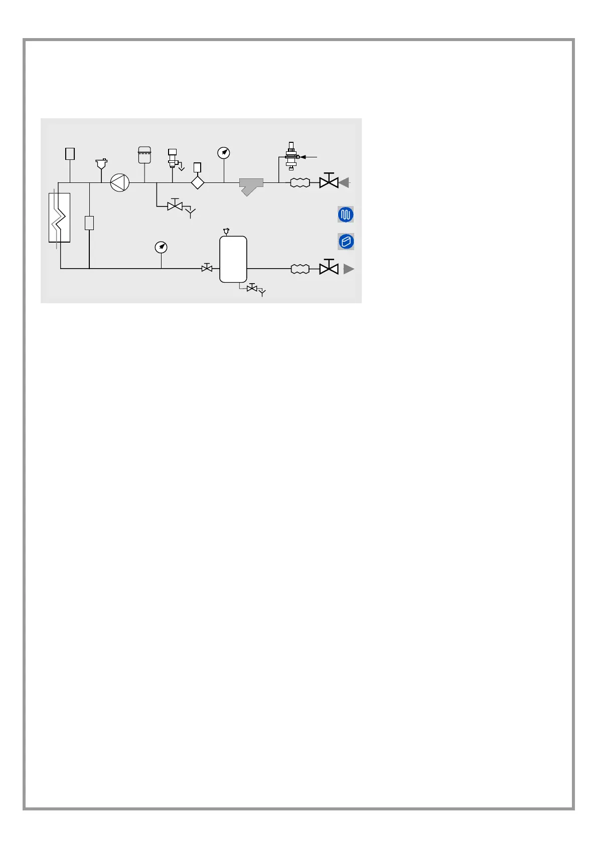
DIAGRAM OF RECOMMENDED USE SIDE CONNECTION
Depending on the type of machine and the selected setup, some components may be integrated into the unit.
P
9
11
14
8
F
2
3
5
12
7
6
4
8
1
10
13
P
7
1. Charged system pressure switch
2. vent
3. circulating pump / pump
4. expansion tank
5. safety valve
6. flow switch
7. pressure switch / thermometer
8. filter
9. filling valve
10. antivibration joints
11. user side exchanger
12. Differential pressure switch
13. Discharge cock
14. inertial storage tank
The accumulation tank is necessary in the event of the following:
• the water in the system is very low
• the unit will not be used in a private house (in an industrial process or other)
WINTER CONDENSATION
When a heat pump is running it produces a considerable
amount of water due to the defrosting cycles of the external
coil.
The condensation must be eliminated in a manner to avoid
wetting pedestrian areas.
The units are equipped with a condensation collection
basin: connect both connections to guarantee the
disposal.
The connection must not transfer mechanical stresses and
it must be performed paying attention to avoid the
damaging of the unit discharge connection.
With extensive very cold outdoor temperatures,
condensation could freeze and block the flow, causing a
slow build-up of ice; therefore special attention must be
paid to eliminating condensation, raising the unit off the
ground and evaluating whether antifreeze elements should
be installed (also to protect the connection sleeve to the
basin) .
THE FROST OF THE CONDENSATE WATER CAN LEAD
TO UNIT IRREVERSIBLE DAMAGES.
 Loading...