pag 47
Application: Unit for radiant panels
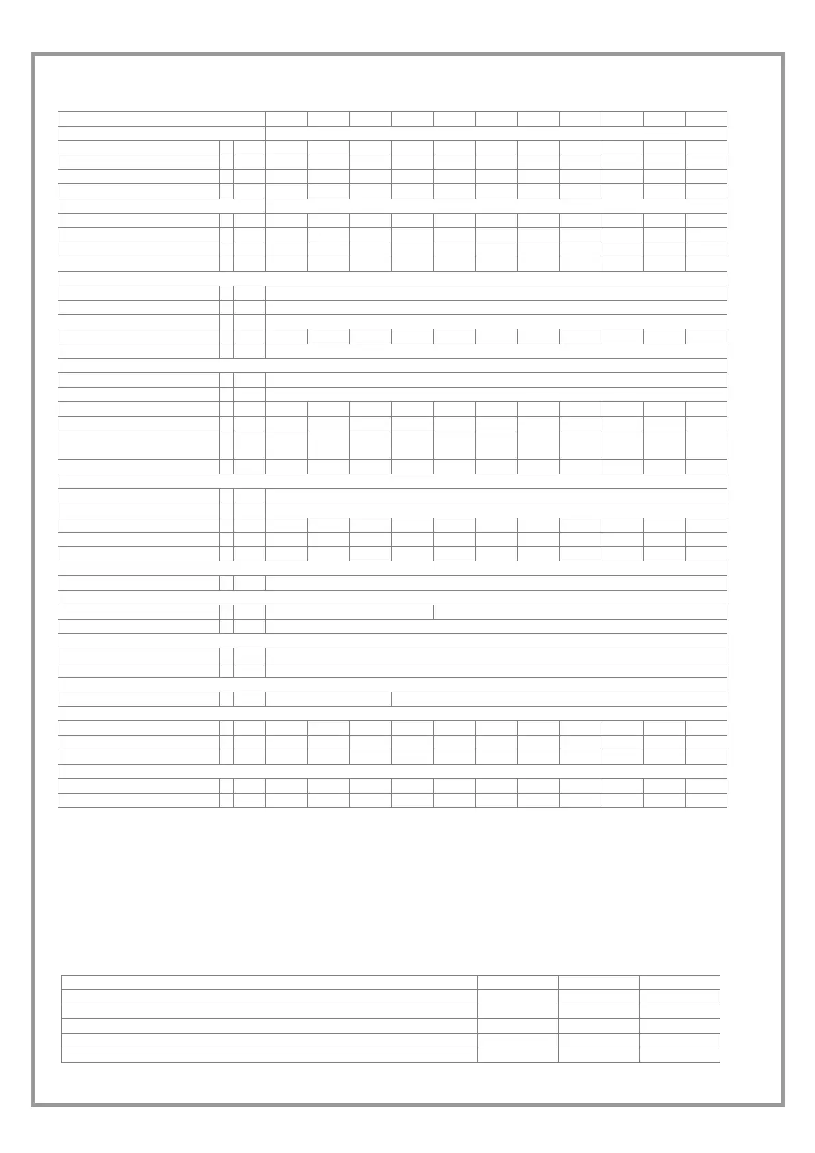
Size 17 21 31 41 51 61 71 81 91 101 121
COOLING
Cooling capacity 1 kW 8,07 8,83 10,5 13,8 17,7 21,9 26,2 29,6 33,6 37,5 42,3
Compressor power input 1 kW 1,42 1,53 1,94 2,33 3,04 3,88 4,81 5,17 5,94 6,87 7,82
Total power input 2 kW 1,43 1,54 1,95 2,34 3,05 3,89 4,82 5,18 5,95 6,88 7,83
EER kW 5,64 5,73 5,38 5,9 5,80 5,63 5,44 5,71 5,65 5,45 5,4
HEATING
Heat output 3 kW 6,95 7,5 9,36 12 16,1 19,7 24,7 26,5 31 36,7 41,6
Compressor power input 3 kW 1,28 1,4 1,77 2,27 2,88 3,53 4,47 4,89 5,62 6,41 7,28
Total power input 2 kW 1,29 1,41 1,78 2,28 2,89 3,54 4,48 4,9 5,63 6,42 7,29
COP kW 5,39 5,32 5,26 5,26 5,57 5,56 5,51 5,41 5,51 5,72 5,71
COMPRESSOR
Type of compressors SCROLL
No. of Compressors 1
Std Capacity control steps 1
Refrigerant charge (C1) kg 0,9 0,9 1,1 1,1 1,4 1,6 1,9 2,5 3,2 3,1 3,3
Refrigerant circuits 1
INTERNAL EXCHANGER
Type of internal exchanger 4 PHE
No. of internal exchangers 1
Water flow rate 1 l/s 0,39 0,42 0,5 0,66 0,85 1,05 1,25 1,41 1,61 1,79 2,02
max Water flow rate l/s 0,64 0,7 0,84 1,1 1,41 1,74 2,09 2,36 2,68 2,99 3,37
Useful pump discharge
head
kPa
46.9 43.1 43.4 28.3 20.4 41.0 33.3 24.3 17.8 83.5 41.8
Water content l 0,6 0,6 0,8 0,8 0,9 1,1 2,2 2,5 2,9 2,9 3,2
EXSTERNAL EXCHANGER
type of external exchanger 4 PHE
No. of exsternal exchangers
1
Water flow rate l/s 0,45 0,49 0,59 0,77 0,99 1,23 1,48 1,66 1,89 2,12 2,39
max Water flow rate l/s 0,76 0,82 0,99 1,28 1,65 2,05 2,47 2,77 3,15 3,53 3,99
Pressure drop kPa 28 31 31 43 49 51 59 52 53 75 80
Connections
Water fittings 5 1"GAS F
EXPANSION VESSEL
Expansion vessel capacity l 1 2
No. of expansion vessels 1
HYDRAULIC CIRCUIT
Max water side pressure kPa 550
Safety valve calibration kPa 600
POWER SUPPLY
Standard power supply 230/1/50 400/3/50+N
Dimensions
Length mm 402 402 402 402 402 573 573 573 573 573 573
Depth mm 602 602 602 602 602 604 604 604 604 604 604
Height mm 785 785 785 785 785 858 858 858 858 858 858
STANDARD UNIT WEIGHTS
Shipping weight kg 79 81 84 88 96 112 126 143 159 160 166
Operating weight kg 81 83 86 90 98 115 129 147 163 164 170
(1) data referred to the following conditions :
external exchanger water = 30/35°C
internal exchanger water = 23/18°C
(2) The total absorbed power is obtained adding the compressors absorbed power + the power absorbed by the auxiliary circuit.
(3) data referred to the following conditions :
WATER TO INTERNAL EXCHANGER 40/45°C
External exchanger inlet water = 10°C
The water flow in the external exchanger is the same of the cooling operation.
(4) PHE = plates
(5) water connections both source side and utility side
SETTING THE CUT-OUT DEVICES AND CONTROLS
On Of
alue
High pressure safety switch kPa 4200 3300 --
Low pressure safety switch kPa 200 350 --
Antifreeze protection °C 4 6,5
Max compressor starts per hour Nr -- -- 10
Safety discharge thermostat °C -- -- 120
 Loading...