SERVICING
Your CMC PT-35 is operated with a hydraulic actua-
tor, which is located inside the unit. It is filled with the
correct amount of hydraulic fluid and tested at the fac-
tory. If it becomes necessary to add fluid to the actuator,
use #2216 Mystic or equivalent, SAE 20 or 30 non-de-
tergent oil. Follow the procedure below for adding fluid
and bleeding the system:
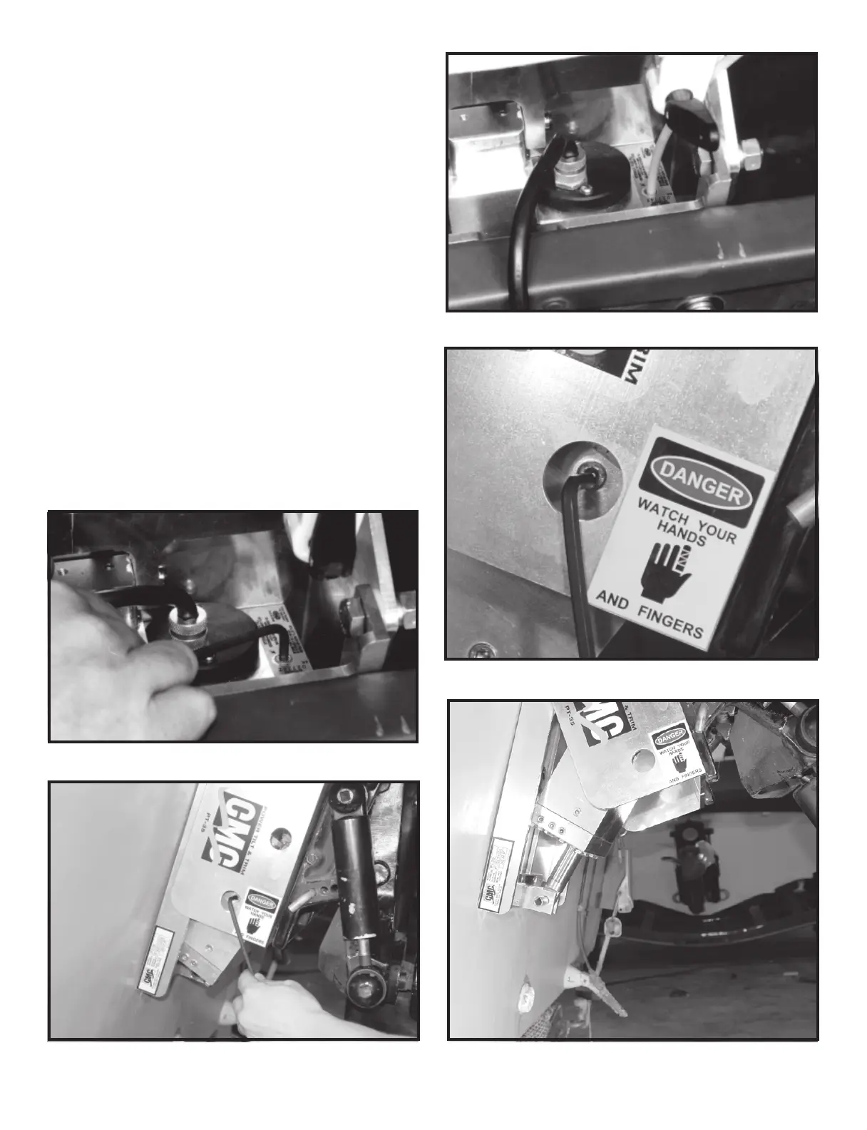
First, trim the PT-35 all of the way down. Remove the
1/8" brass socket filler plug with a 3/16" hex key wrench
(Fig. 17). Next, with the same wrench, remove the level
plug. You can access this plug through the lower ma-
chined hole on the port side motor rail as shown in Fig.
18. Pour fluid into the actuator through the filler hole
until fluid runs out of the level hole on the side of the
actuator (Fig. 19). Run the actuator until the ram is fully
extended and the motor bogs down (the PT-35 is all the
way up). Then retract the ram completely until the mo-
tor bogs down (trim the PT-35 all the way down). Re-
place the level plug (Fig. 20). Tilt the PT-35 out until the
ram is extended 2 to 3 inches out of the actuator
(Fig. 21).
Replace the filler plug.
If preferred, the above procedure can be executed with
the actuator completely remove from the PT-35. Please
see the next page for the removal of the actuator.
Tighten the lower bolts (Fig. 12). All of the mounting
bolts should be checked for tightness frequently.
CONNECTING TO POWER SOURCE
Step 11: Find a good location for the up-down toggle
switch. This toggle switch should be located
for easy access while operating the throttle.
Use a 1/2 inch drill to drill a hole at the cho-
sen location taking care not to damage wires
or brackets (Fig. 13)
Step 12: Locate the wires on the wire assemble; 1. One
labeled up; 2. One labeled down; 3. One la-
beled 12V. Position the switch so the terminal
posts are on the side nearest you. Connect the
down wire terminal to the top post. Connect
the 12V wire terminal to the center post. Con-
nect the up wire terminal to the bottom post
(Fig. 14).
Step 13: Push the toggle switch through the 1/2 inch
hole that you previously drilled. Place the up-
down switch plate and rubber boot with nut
on the switch (Fig. 15).
Step 14: Connect the 2-wire male connector from the
hydraulic power unit to the female 2-wire con-
nector at the end of the wire assembly
(Fig. 16).
Find a dry location for the two 40 amp relays and se-
cure them there.
NOTE: If your boat is used in a corrosive environ-
ment such as saltwater and you cannot locate a dry
place for the relays, you can secure the relays inside
the cowling of your engine. Instead of connecting the
positive and negative ring terminals of the wire as-
sembly to the battery, connect them to the starter
where the positive and negative leads from the bat-
tery are attached.
Step 15: Connect the ring terminal labeled POS to the
positive battery terminal and connect the ring
terminal labeled NEG to the negative battery
terminal.
The PT-35 is now ready for operation. When you push
the toggle switch lever up, the PT-35 should run up. When
you push the switch down, it should run down.
CAUTION: WHEN TRAILERING IT IS RECOMMENDED
TO SUPPORT THE PT-35 WITH A TRANSOM SAVER
DEVICE. WHEN RUNNING THE PT-35 DOWN TO THE
SUPPORT, JUST MAKE CONTACT WITH IT. DO NOT
CONTINUE TO LUG IT DOWN AFTER INITIAL CON-
TACT HAS BEEN MADE OR DAMAGE TO THE, PT-35
WILL OCCUR.
- 4 -
- 5 -
Fig. 16
Fig. 13
Fig. 14
Fig. 15 Fig. 18
Fig. 19
Fig. 20
Fig. 21
Fig. 17
Fig. 12
 Loading...