8 Online Instructions: c-m-p.com/tech
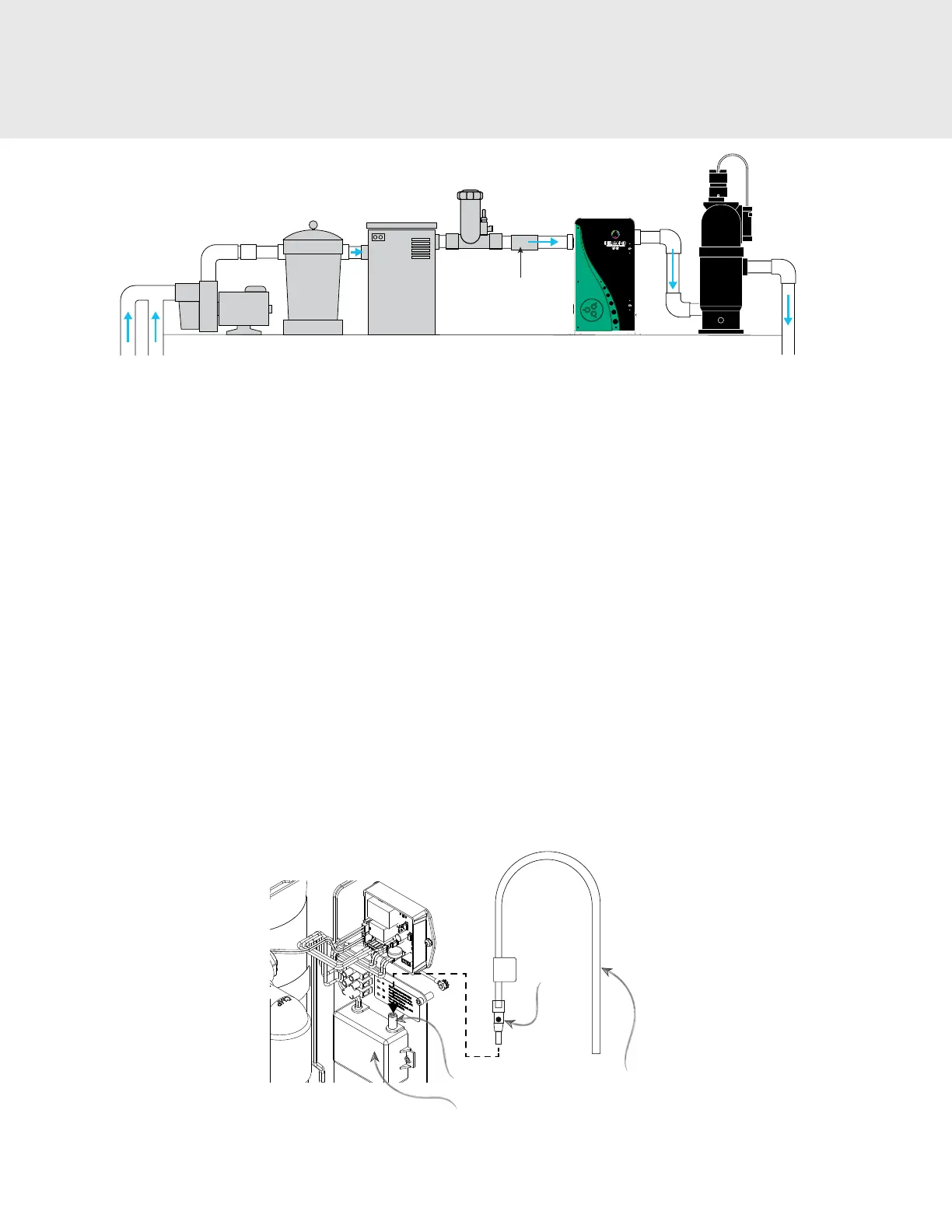
HeaterFilterPump
DEL
AOP 25/40
MDV XL
(if required)
Backflow
Check Valve
(optional)
Return to Pool
Powerclean
Tab Feeder
Figure 5: DEL AOP Typical Location in Pool Plumbing Loop
2C-2. About the Mixing De-gas Vessel (optional)
Under normal operation, bubbles will appear in the return ow to the pool. To remove the bubbles from the ow, an
accessory Mixing De-gas Vessel, or MDV, can be installed downstream of the DEL AOP. The MDV is designed for use with the
DEL AOP and is recommended on indoor, covered, or vinyl-lined pools. It should also be used if a tab feeder in installed after
the AOP system. For more information, please visit c-m-p.com/support.
2C-3. Above Water Level Installation: Water Backow Check Valve
If the pool equipment is mounted above the water line, install a 2 inch CMP Hydroseal check valve (25830-400-000) between
the pump outlet and the inlet of DEL AOP to prevent the pump from draining and losing prime when not in use.
2C-4. High Return Pressure Installation: Orice Plate (AOP 25 ONLY)
The AOP 25 will function best when the pool equipment is above water level and there are no accessories introducing
additional pressure on the return line. In cases where the return line pressure prevents proper operation, an orice plate may
be added to the inlet of the spring-loaded check valve. This can improve injector performance.
1. Flow Meter Test (Fig 6a) : If there is any question whether the injector is performing properly, a ow meter is provided in
the parts kit to check for proper suction through the ozone cell.
a. Operate the pool in the mode expected to introduce the highest return pressure.
b. Remove the air lter from the ozone module.
c. Attach the tubing from the ow meter to the ozone module.
d. Hold the ow meter vertically and observe that the ball is above the “MIN” line. The ball may be bouncing but
should average mostly above the line. The “MAX” marking can be ignored for this test.
e. If the ball is not moving or is consistently below the “MIN” line, Install the orice plate.
Air Filter
Ball
Flow Meter
Assembly
Ozone Module
Figure 6a : Flow Meter Test
2. INSTALLATION