Do you have a question about the CNCPROM 110ST-M06030 and is the answer not in the manual?
Guidelines for safe installation to avoid damage and hazards.
Precautions for safe and correct wiring procedures.
Safety rules to follow during the operation of the equipment.
Key points to check and be aware of during inspection.
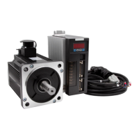
Details on inspecting the servo drive and motor for proper function and appearance.
Information about the manufacturer's identification label for the AC servo driver.
Description of the components and layout of the servo driver's front panel.
Overview of the AC servo motor driver's technical specifications and features.
Guidelines and conditions for installing servo motors in various environments.
Explanation of how to identify forward and reverse rotation directions of the motor.
Table showing compatibility between KRS drive models and servo motor models.
Explains the overall system setup and wiring configurations for servo drives.
Illustrates the detailed wiring connections for the servo driver.
Provides essential instructions and precautions for correct wiring practices.
Details the required wire types, sizes, and specifications for terminals.
Explains the terminals for high-power connections on the servo driver.
Describes the CN1 communication interface, including port numbers and types.
Lists the pin assignments and corresponding numbers for the CN1 port.
Detailed pinout and function description for the CN1 communication port.
Explains the different types of connections supported by the CN1 port (RS-232, RS-485).
Details the CN2 control interface, its functions, and port numbers.
Lists the pin assignments and corresponding numbers for the CN2 port.
Provides instructions and functional descriptions for the CN2 control port pins.
Explains the different types of interfaces supported by the CN2 port (digital input/output).
Describes the CN3 interface for connecting the encoder and its pin assignments.
Details the standard wiring configurations and recommendations for the servo system.
Describes the servo drive's front panel and its control buttons.
Explanation of how to use the mode switch for navigating the drive's functions.
Guide on how to operate the drive in monitoring mode to view parameters.
Instructions for using the auxiliary mode to access specific functions like alarms.
A list of auxiliary functions available in the drive, with brief instructions.
Procedure for querying alarm records using the Fn000 function.
How to permanently save user-modified parameters to EEPROM.
Guide for performing trial operations or inching mode on the servo motor.
Steps and methods for clearing alarm conditions on the servo drive.
Process for initializing drive parameters to default or factory settings.
How to clear the position deviation value during operation.
Setting the output ports to a forced high or low level.
Procedure for correcting the torque command voltage simulation.
How to perform simulation correction for speed command voltage.
Steps for correcting the busbar voltage measurement.
Procedure for calibrating the drive's temperature sensor.
How to initialize or clear the alarm records.
Procedure for setting the encoder zero point.
How to access and operate the drive using user parameter mode.
Guide on selecting specific parameter numbers for modification.
Steps for modifying existing parameter values.
How to operate the parameter settings panel.
A comprehensive list of all available parameters, their ranges, and default values.
Lists and describes system-related parameters for the drive.
Parameters specifically for controlling the servo motor's position.
Parameters related to controlling the servo motor's speed.
Parameters for controlling the servo motor's torque.
Parameters for extended control functions of the servo drive.
Detailed system parameters, including motor code and control mode.
Detailed system parameters, including motor code and control mode.
Explains the functions and specifications of the SigIn and SigOut ports.
Explains the functions and specifications of the SigIn input ports.
Explains the functions and specifications of the SigOut output ports.
Guide on operating the monitor panel to view drive status.
List of parameters that can be monitored and their corresponding display codes.
Steps for clearing alarms as described in auxiliary mode operations.
Details common alarm codes, their causes, and elimination methods.
Overview of Modbus communication interfaces (RS-232, RS-485) and modes.
Explains the coding schemes used in Modbus communication (ASCII, RTU).
Describes the structure of communication protocols for Modbus.
Lists and explains common command codes used in Modbus communication.
Instructions for reading multiple registers using Modbus commands.
Procedure for writing data to a single register via Modbus.
Explains the diagnostic function and its related command codes.
Instructions for writing data to multiple registers using Modbus.
Communication addresses for accessing servo parameters and status information.
Details on how gain switching is implemented and related parameters.
Explains how to switch between different control modes (position, speed, torque).
Guide on switching between position and speed control modes.
Instructions for switching between position and torque control modes.
How to switch between speed and torque control modes.
Time sequence diagrams for servo driver operations (ON/OFF, alarms).
Sequence of actions when the motor is resting and powered ON/OFF.
Sequence of actions during motor operation when powered ON/OFF.
Time sequence of events when a servo alarm occurs during ON state.
Information about the electromagnetic brake function and its usage.
Details on regenerative braking resistors and their importance.
Procedures and parameters for setting the origin point (homing).
Step-by-step guide for performing origin point operations.
Time sequence diagrams for origin return trigger conditions.
Combinations of origin models and their time-series regression.
Details and parameters for internal position control functionality.
| Brand | CNCPROM |
|---|---|
| Model | 110ST-M06030 |
| Category | Servo Drives |
| Language | English |