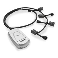
9. Locate front cylinder injector connector from left side of motorcycle, Figure 5. Pull Red lock tab upward,
see Figures 6 and 7, depress black tab under it and pull connector straight up and free from injector. Mate
the longer PPT female connector to the front injector and seat firmly, see Figure 8. Mate the PPT male
connector with stock female connector and seat firmly together. Depress red lock tab on stock connector.
10. Be sure all connectors are securely installed on injectors and snapped together and "RED" lock tabs are
seated in place. Carefully tuck the connectors back towards cylinder heads and under frame rail.
11. Locate the front O
2
sensor connector under plastic shroud at front of engine, and disconnect stock male
and female connectors, it may be necessary to open up wire retaining ring for proper slack to work on
connectors. Mate corresponding PPT female O
2
connector with the original male O
2
connector. Connect
PPT male O
2
connector to original O
2
female connector on Victory harness, see Figure 9. Be sure to
secure O
2
sensor connectors to wire loop retainer and secure PPT harness along the front cast frame
member to existing harness with (3) 6 inch zip tie. Install (2) 6 inch zip ties along the left upper cast
frame rail to secure front O
2
and Injector harness to existing wiring harness, Figure 4.
12. Locate rear O
2
sensor connectors and disconnect. Mate each corresponding stock connector with PPT
connectors as in Step 11, see Figure 10. Be sure connectors seat firmly and harness runs next to
vacuum line. Zip tie harness to vacuum line to prevent it from coming in contact with exhaust, Figure 11.
13. Set fuel tank back onto frame behind front rubber mounting lugs and reinstall quick connect fuel line
securely, 4 pin electrical connector and two vent lines at left rear of tank. Lower fuel tank back into
position carefully slide it forward until it engages front mounting lugs. Be sure to install both M8 mounting
bolts and ground wire previously removed. Be sure all fasteners are tightened to factory specifications.
14. Place the seat back on motorcycle and install ground wire for Powrpro Tuner using left seat bolt. Install
right seat bolt and tighten securely.
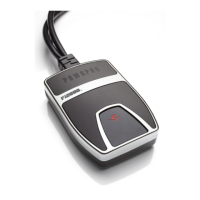
15. Verify that the module has power and connections have been made correctly; watch the clear window on
the FI housing and turn "ON" the key ignition and set the handlebar run switch to "ON", confirm that the
Red LED turns on. On some models the Red light will turn off after 4-5 seconds as the fuel pump cycles
off, which is OK. If you do not see a Red light, it may be necessary to wait for the alarm to reset (if
applicable) and try again. Also confirm the side stand is up, bike is in neutral, and clutch is in. Start the
bike and confirm the LED remains on solid Red. NOTE: Make sure ignition is turned off before attempting
to change any Fi2000 harness connections if no Red light is seen. For access to the Blue Tooth Tuning
App on the module, please download the PowrPro Black App to your smart device, Android 4.3 & later or
Apple iOS 5.0 & later operating systems. Once the app is installed, make sure the motorcycle is in
neutral and start the engine, use the connect button within the app and the Blue light on the Fi module
window will light up during pairing connection and remain solid Blue while paired and connected with
respective Android or Apple Device. Once the app has been used and settings saved and disconnected
through the app, the Blue light will turn off, and the PowrPro Black will be ready for continued service on
the motorcycle.
16. Remove the backing from the Velcro and place the PPT between the main ECU and harnesses, and tuck
stock harnesses neatly back into place, see Figure 11.
17. Confirm all fasteners have been retightened to factory specifications. Reinstall left and right side covers
below seat area.
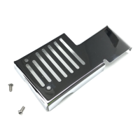
18. Place left and right triangular engine side covers back into place between cylinder heads.
TROUBLE SHOOTING: If you have any problems refer to Step 15 in the main body of the instructions.
 Loading...