• Functional Description
The Cobra models MRF55 and MRF75 are Marine band FM Radio transceivers operated in the
frequency range 156.025MHz to 163.275MHz with WX and DSC. Functional as follows:
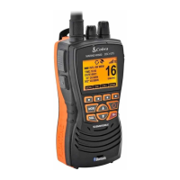
1. MRF55: Channel Up / Down, Emergency channel key CH16/9, WX/UIC key, Channel Scan key, TX
power HI/Low key, Dual watch channel key, Call/set key, Distress key, Squelch control volume, DC power
ON/Off and Audio Volume control, External Speaker Jack and GPS Jack, PTT key.
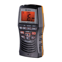
2. MRF75: Channel Up / Down, Emergency channel key CH16/9, WX/UIC key, MEMO Channel Scan key,
TX power HI/Low key, Tri watch channel key, Call/set key, Distress key, Squelch control volume, DC
power ON/Off and Audio Volume Up/Down control, PA Function, External Speaker & PA Jack and GPS
Jack, PTT key.
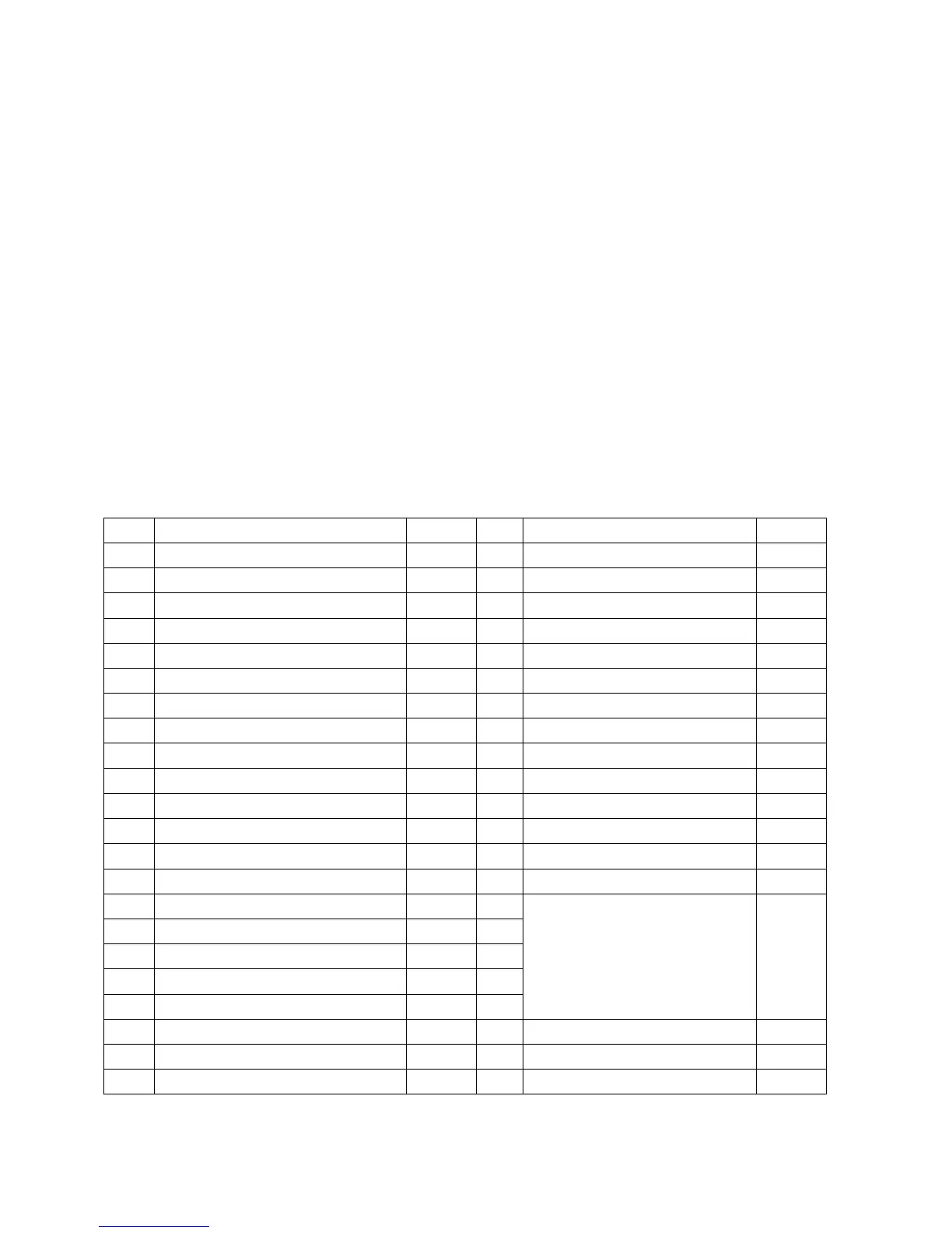
• MCU Description
The MCU uses Toshiba’s TMP86CM47U micro-controller, there are 32k X 8bits ROM and 1k X
8bits RAM, LQFP44 pins package. These pin assignment as below table:
PIN Description Model PIN
Description Model
1 Vss = GND 55/75 23 Control LCD SDI data pin 55/75
2 X-in, crystal 8 MHz 55/75 24 WX alert data pin detect 55/75
3 X-out, crystal 8 MHz 55/75 25 TX Hi / low power control 55/75
4 Test, connect to GND. 55/75 26 Keys scan pin 55/75
5 Vdd, +5VDC input 55/75 27 Keys scan pin 55/75
6 DC power on control F75 28 Beep tone Hi/low control 55/75
7 TX on/off control (on = low) 55/75 29 Digital volume data pin F75
8 Reset pin 55/75 30 Digital volume clock pin F75
9 DC power on key scan F75 31 Open 55/75
10 LCD backlight control 55/75 32 EEprom clock pin 55/75
11 LCD backlight control 55/75 33 RX/TX signal indication 55/75
12 NMEA (GPS data) input 55/75 34 Pull high to +5VDC 55/75
13 EEprom data pin 55/75 35 AVDD (connect +5VDC) 55/75
14 Volume down key scan F75 36 AVSS (connect to GND) 55/75
15 Volume up key scan F75 37
16 Squelch output control 55/75 38
17 Inhibit audio when DSC on 55/75 39
18
Control LCD driver A0 data pin
55/75 40
19 PLL STB. HI=F75, Low=F55 55/75 41
Pin 37 to 41 for 1300Hz and
2100Hz FSK generator.
55/75
20 PLL clock data output 55/75 42 PLL data output 55/75
21 Beep tone generator 55/75 43 DSC detect pin 55/75
22 Control LCD CS1 pin 55/75 44 Squelch input detect 55/75
Remarks: MCU pin19 (BUS14) for MRF55 and MRF75 models select by resistor R371 and
R340 control. R371 open for MRF55 model, R340 open for MRF75 model selection.
 Loading...