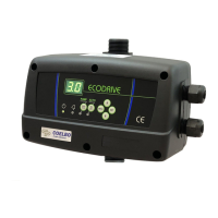
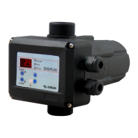
The ECODRIVE is a compact automatic control device designed for the automation of single-phase pumps. It features an electronic system managed by software, responding to the rigorous requirements of efficiency and safety set by leading pump manufacturers. The device includes a frequency inverter that regulates the pump's speed to maintain constant pressure, independently of the flow rate.
Function Description:
The ECODRIVE ensures constant pressure and significant energy cost reduction by supplying the system with the precise and necessary output at all times, achieving maximum energy efficiency. The system incorporates a 2-digit LCD screen for easy and intuitive parameter configuration. Once configured, the device manages the pump's start-up and the frequency inverter.
To establish the ideal pressure for an installation, the following criteria should be considered:
- Hm (Max. water column height in m): This depends on the number of floors and corresponds to the height from the pump to the last floor. Approximately 10 m of height equals 1 bar (0.98 bar).
- Pw (Available minimum pressure in last floor): Usually 1.5 bar.
- Pc (Pressure drop): Can be considered with a simplified criterion of 0.033 bar/m.
- Prmin (Minimum resultant pressure): The sum of the previous pressures, representing the pump's operating pressure.
- Example for a 5-floor building (15 m) with the pump at level 0:
- Hm = 15 m ≈ 1.5 bar
- Pw = 1.5 bar
- Pc = 15 x 0.033 bar ≈ 0.5 bar
- Prmin = 1.5 + 1.5 + 0.5 = 3.5 bar
Important Technical Specifications:
- Power supply: 1x127-230~V +10% -20% V
- Frequency: 50/60 Hz
- Max. current per phase: 7.5A
- Max. peak current: 20% during 10"
- Max. operating pressure: 15 bar
- Max. set pressure: 0.5÷8 bar
- Protection Index: IP55
- Max. water temperature: 40°C
- Max. ambient temperature: 0-50°C
- Max. flow rate: 8,000 l/h
Usage Features:
- Hydraulic Connections:
- Inlet and outlet connections are G 1" male s/ ISO 228.
- A check valve is indispensable on the pump's suction side.
- The device must be installed vertically, connected directly to the pump's discharge (G 1 1/4" / NPT 1 1/4" male thread) and to the network (G 1 1/4" / NPT 1 1/4" male thread).
- An expansion tank of at least 5 liters capacity is essential to prevent continuous start-stops due to leaks and water hammer.
- Electrical Connections:
- Before any internal manipulation, disconnect the device from the electrical supply and wait at least 2 minutes to avoid electrical discharges.
- Use H07RN-F cables of appropriate cross-section (power supply: ≥ 1 mm² (max. 2.5 mm²); motor connection: ≥ 1 mm² (max. 2.5 mm²) depending on cable length).
- Verify line voltage is 127-230V.
- Connect the general power supply (ensuring an effective ground connection) to N and L via a magnetothermic switch suitable for the installed power and in the OFF position.
- The ground conductor must be longer than the phase conductors and be the first to be connected during assembly and the last to be disconnected during disassembly.
- Connect the pump to V and W.
- WARNING: Incorrect connections can cause irreparable damage to the electronic circuit.
- Control Panel (LCD Screen):
- 2-digit display shows instantaneous pressure (bar), instantaneous current consumption (A), and minimum frequency (Hz).
- MANUAL START-STOP button: To start the pump manually.
- MENU button: To enter or exit the menu.
- Up/Down arrows: To increase or decrease programmed values.
- SET button: To save selected values. Each press presents a new field in the CONFIGURATION MENU. Press MENU to exit.
- ON/OFF button: Toggles between AUTOMATIC and MANUAL modes.
- LED Indicators:
- LINE (green): Electrical supply, lit when connected.
- FAILURE (red): Blinks or stays lit depending on the type of fault.
- PUMP (yellow): Lit when the pump is working. Off when the pump is stopped or no line voltage.
- AUTOMATIC (green): Lit in automatic mode.
- Start-up (Plug&Play):
- Prime the pump.
- Connect the device to the electrical network. All indicators will light up momentarily and then turn off.
- The screen will show "SP" (set pressure) and its default value of 2.0 bar (alternating display for 1"/5").
- Adjust the nominal pump current (see Configuration section).
- Adjust the desired set pressure using the up/down arrows.
- Press the AUTO button. The AUTO ON/OFF LED will light up. The default display shows instantaneous pressure. In automatic mode, the display can be changed using the up/down arrows to show:
- P: instantaneous pressure (bar).
- FR: instantaneous frequency (Hz).
- A: instantaneous current consumed (A).
- ºC: instantaneous power module temperature (ºC).
- Configuration Menu:
- Press MENU for 3 seconds to enter configuration.
- Set the nominal pump current (A) using up/down arrows (0-7.5A, found on motor plate). Press ENTER to validate.
- Increase the lower limit of the main pump's rotation speed (FL) using up/down arrows (30-35 Hz, default 30 Hz). Press ENTER to validate and exit.
- Press AUTO ON/OFF to exit manual mode.
- Operation Data and Alarms Register:
- Simultaneously press MENU + ↑ for 3 seconds to access the register.
- Use ENTER to navigate through the sequence. Press SET again to return to the main display.
- Records include:
- HF (REGISTER HOURS): Total operating hours of the device.
- HP (REGISTER PUMP HOURS): Total operating hours of the pump.
- CF (REGISTER STARTS): Number of operation cycles (start and stop).
- Cr (REGISTER SWITCH): Number of connections to the electrical network.
- A1 (ALARM COUNT DRY RUN): Number of dry-running alarms.
- A2 (ALARM COUNT I MAX): Number of overcurrent alarms.
- A3 (ALARM COUNT DISCONNECTED PUMP): Number of disconnected pump alarms.
- A4 (ALARM COUNT LEVEL): Not available on this model.
- A5 (ALARM COUNT PRESSURE SENSOR): Number of pressure sensor faults.
- A6 (ALARM COUNT TEMP): Number of alarms due to excessive temperature.
- A7 (ALARM COUNT SHORTCIRCUIT): Number of short circuit alarms.
- A8 (ALARM COUNT OVERVOLTAGE): Number of overvoltage alarms.
- A9 (ALARM COUNT UNDERVOLTAGE): Number of undervoltage alarms.
- All records are saved even if the device is disconnected from the electrical supply.
- Note: For quantities over 2 digits, they will appear on consecutive screens after each ENTER.
Maintenance Features (Alarms):
In case of simultaneous alarms, exit automatic mode and go to manual mode by pressing AUTOMATIC ON/OFF (PUMP LED will turn off). Use ↑↓ keys to view successive alarms. After viewing, press ENTER to return to MANUAL mode.
- A1 DRY RUNNING (★ Failure verification - Final failure):
- Description: System detects dry running for >10 seconds, stops pump, activates ART (Automatic Reset Test).
- System Reaction: After 5 minutes, ART restarts pump for 30 seconds. If water lack persists, it retries every 30 minutes for 24 hours. If still no water, pump remains permanently out of order.
- Solution: Verify hydraulic network feeding. Prime pump using START/STOP (AUTOMATIC LED off). Check nominal current consumption in setup menu.
- A2 OVERCURRENT (★ Failure verification - Final failure):
- Description: Pump protected against overcurrents based on intensity set in installation menu, usually due to pump or electrical supply dysfunctions.
- System Reaction: Pump automatically stopped. System attempts 4 restarts. If locked after 4 attempts, pump remains definitively out of order.
- Solution: Verify pump status (e.g., impeller blockage). Verify intensity values in configuration menu. Restore operation by reconfiguring current value.
- A3 DISCONNECTED P. (Final failure):
- Description: Electronic safety system for no-load detection.
- System Reaction: Device is disconnected.
- Solution: Verify motor winding and pump consumption. Restore operation by configuring adequate intensity value in "INSTALLATION" menu.
- A5 TRANSDUCER (Final failure):
- Description: Transducer damages shown on LCD screen.
- System Reaction: Device operation interrupted.
- Solution: Contact technical service.
- A6 EXCESSIVE TEMP. (Final failure):
- Description: Cooling device keeps INVERTER in optimum working conditions.
- System Reaction: If excessive temperature is reached, the system takes the inverter out of service, and consequently the pump.
- Solution: Verify water temperature (<40 ºC) and ambient temperature (<50ºC). Contact technical service.
- A7 SHORTCIRCUIT (Final failure):
- Description: Electronic system for protection against short circuits and excessive current peaks.
- System Reaction: Pump stops for 10", then restarts (4 attempts). If problem persists, pump remains definitively out of order.
- Solution: Check pump. If problem persists, contact the manufacturer.
- A8 OVERVOLTAGE - A9 UNDERVOLTAGE (★ Failure verification):
- Description: Electronic safety system against overvoltages and too low supply voltages.
- System Reaction: System stops until adequate voltage is reached. System automatically restored.
- Solution: Check electric supply.
- Blank screen:
- Solution: Check electric supply 127-230 V.