ENGLISH
OPERATION
CONSTRUCTIONCHARACTERISTICS
TECHNICALCHARACTERISTICS
HYDRAULIC CONNECTION (Fig.1)
ATTENTION.
ATTENTION.
ELECTRIC CONNECTION (fig. 2)
WARNING.
STARTING.
POSSIBLE PROBLEMS
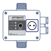
The OPTIMATIC controller orders the automatic start and stop of
the water pump when opening or closing any tap or valve of the
installation.When the water pump starts, it keeps running while it
exists any tap opened in the system, giving a constant flow an
pressure tothe network.
- Inlet male G 1'.’
- Outlet male G1'.'
- Special non return valve which avoids surges
- Security system avoiding the possibility for the machine to work
without water
- Pressure gauge
- Tension LED (POWER)
- Security systemLED (ALARM)
- Pump-working LED (ON)
- Manual startswitch(RESET)
- Integrated socket for motor connection according toCDIN-IEC
884-1.
- Cable with plugDIN 49 441 forconnection to theelectric supply.
- Tension: ~220/240 V
- Max. Intensity: 16(8)A
- Frequency: 50/60 Hz
- Protection: IP44
- Max. temperature of water: 60° C
- Max. Flow: 10.000 l/h
- Starting pressure: Type F15: 1,5 bar
Type F22: 2,2 bar
Type R:1,5 bar-2,5 bar
- Max. pressure for use: 10 bar
- Max. Pump power: 230V: 2HP(1500W)
Before proceeding with hydraulic connection it is essential to prime
the pump correctly. The electronic controller should be installed
always in horizontal position with the overmolded arrow pointing
to the top, connecting the inlet opening (male G1”) directly to the
pump and the outletopening (male G1” ) to the network.
Avoid oulet non return valves. The following
accessories are recommended: flexible with disassembling link for
network connection, protecting the set from possible flexion
charges and vibrations. Ball valves which allows the isolation of the
pump from the installation.
The water column between the pump and the
highest point of the installation depends on the starting pressure.
Here below, we give you a list with the height of the column and
the maximum pressure which must supplies the pump.
The adjustment of the starting pressure in type R is made by the
screwplaced in the back side of the device (fig.3)
Check the power supply to be ~220/240V. Connect the pump to
OPTIMATIC through the SCHUKO SOCKET. The OPTIMATIC can be
used with a single-phasepump with electrical input under 10 A.
Bad connections mayspoil the electroniccircuit.
H07RN-F 3G1 type cables (Ø8÷11mm) must be used in order to
ensureIP 44 protection.
1.-Be sure that the pump is primed, then slowly open a tap.
2.- Connect the electronic controller to the electric supply. The
tension LED will lit (POWER).
3.-The pump starts working automatically and within a
period of 20-25 seconds the pressure gauge will reach
approximately the maximum pressure provided by the pump.
During its working the corresponding LED (ON) will be on.
4.-Close the tap indicated on point 1. After 10-12 seconds the
pump will stop. The tension LED (POWER) will be the only one to
remainon.
Any problem after this procedure will be due to a defective pump
priming.
1.-
a) Water leak higher than 1,5 l/min. at some point:
Check the installation, taps, WC, etc.
b) Manual start switch (RESET) is blocked:
Act on it several times,in case the problem persists consult
your dealer.
c) Breakdown on the electronic card: proceed to its substitution.
d) Incorrect electric connection: check the connections
according to Fig.3.
2.-
a) Not enough water supply, the security system has been
activated and the LED (FAILURE) is on: check the water supply
and restartthe pump through the resetswitch(RESET).
b) The pump is not hydraulically primed. The safety system against
dry operation has been activated and the LED (FAILURE) is on: fill
with water the inlet, drain the water surplus in the installation
opening a faucet located to he same level of the pump - to
diminish the pressure of the water column over the flow sensor -
and restore the operationmode usingthe pushbutton RESET.
c) Pump is blocked: LED (FAILURE) is on, the security system is
activate: when we act on the manual start switch (RESET) the
LED (ON) is activatedbut the pump does not work:
Consult your dealer.
d) Failurein the electroniccircuit:
Switch off power supply, wait a few seconds and turn it on again.
If the pump does not start immediately then replacethe circuit.
e) Not electrical supply: check the proper electric feeding.The
tensionLED (POWER)should be on.
f) Not enough pump pressure:
The security system has been activated and the
corresponding LED (FAILURE) is on. Check that the pump
pressure is the one shown in the hydraulicconnection table.
g) Air in the pump aspiration: the pressure gauge will indicate a
pressure lower than the nominal or constant oscillations. The
security system will act by stopping the pump, the LED (FAILURE)
will be on.
Check the sealing of the connections and O-ring of the
aspiration conduct.
3.-
a) Small leak in some pointof theinstallation:
Verify possible tapor WC tankleaks and repairthem.
?
?
?
Pump does not stop:
Pump does not start:
The pump startsand stops repeatedly:
USING HEIGHT ADJUSTMENT PRESSURE MIN.PUMP PRESS
10m 1,2bar 1,7bar
15m 1,7bar 2,2bar
20m 2,2bar 2,7bar
 Loading...