The SPEEDMATIC SET is a compact automatic control device designed for the automation of pressure groups with either two or three pumps. It features an electronic system managed by software that meets the rigorous requirements for efficiency and safety of leading pump manufacturers. The device incorporates a frequency inverter for the main pump, which regulates its speed to maintain constant pressure regardless of the flow rate. For three-pump models (3010, 3110, 31110), the auxiliary pumps operate with an alternated sequence, managed by power relays.
The system includes an intuitive LCD screen for easy parameter configuration. Once configured, the SPEEDMATIC SET manages the startup of the various pumps and the frequency inverter, ensuring constant pressure and significant energy cost reduction by providing the exact power needed at any given time, thus achieving maximum energy efficiency.
To determine the optimal pressure for installation, consider the following:
- Hm (Max. water column height): This depends on the number of floors and corresponds to the height from the pump to the top floor. Approximately 1 bar (0.98 bar) equals 10 meters of height.
- Pw (Available minimum pressure): Typically 1.5 bar at the top floor.
- Pc (Pressure drop): Can be estimated at 0.033 bar/m.
- Prmin (Minimum resultant pressure): The sum of the above pressures, representing the pump activation pressure.
For example, in a 5-story building (15m) with pumps at ground level: Hm = 15m ≈ 1.5 bar, Pw = 1.5 bar, Pc = 15 x 0.033 bar = 0.5 bar, leading to Prmin = 1.5 + 1.5 + 0.5 = 3.5 bar. Auxiliary pumps should provide a working pressure at least 1 bar higher than Prmin to ensure system operation in case of main pump failure (EW function). In this example, they should provide at least 4.5 bar.
After defining the optimal pressure, the pump group must be sized to provide the necessary flow using appropriate simultaneity coefficients. Common errors during this process include:
- Excessive over-sizing: Only the main pump operates.
- Under-sizing: All pumps operate at full speed without modulation.
- Flow/Pressure ratio 10% identical to the main pump's capacity: In applications with regular consumption over long periods (not typical for residential blocks with oscillating consumption), an equilibrium point may be reached where the main pump alone cannot meet flow and pressure demands. When an auxiliary pump starts, the main pump's speed may drop below the recommended limit, leading to constant operating rotations. While this is not an issue for oscillating consumption, it should be avoided in regular consumption scenarios to prevent reduced pump lifespan.
According to EN-60730-1, the SPEEDMATIC SET is an independent assembly device, type 1B, with Class A software.
Main Characteristics:
- DN inlet and outlet port: G1 1/4" male ISO 228.
- Frequency inverter: For main pump control.
- Power relays: For auxiliary pump control.
- Control and safety system: Against over-intensities and dry operation.
- ART function (Automatic Reset Test): If the device stops due to over-intensity safety system activation, ART attempts to reconnect the group periodically, assuming water supply has been restored.
- EW function (Emergency Working): In case of a serious failure (over-intensity, excessive temperature), EW activates, excluding the affected pump, illuminating the FAILURE light, displaying the failure type on the LCD, recalculating parameters, and allowing the group to continue operating under the best possible conditions.
- Automatic restore system: After a power supply interruption, the system activates in AUTOMATIC mode, retaining configured parameters.
- Volt-free contact: For monitoring alarms displayed on screen, caused by system irregularities or problems.
- Connections for minimum water level detection: In aspiration tank (optional), independent of dry operation safety.
- Internal pressure transducer.
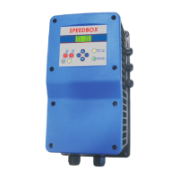
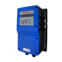
- Control panel (Fig.9):
- LCD screen: For alarm menu with permanent pressure indication.
- START/STOP push-button: To manually operate each pump.
- AUTOMATIC push-button: With LED light.
- Keyboard: For access to programming menu.
- Digital gauge.
- APP function (Adaptability to pressure peaks): Periodically analyzes hydraulic net elasticity, allowing SPEEDMATIC SET to operate with or without expansion tanks without modifying internal parameters. However, expansion tanks are highly recommended for better pressure stability.
- AIS function (Anti-Ice System): If temperatures drop below 5°C, the pump periodically starts to prevent water freezing inside. For ambient temperatures below 0°C, additional measures are crucial to prevent water freezing.
- Operational controls register: Information on working hours, number of starts, power supply connections, and real-time percentage of air in the expansion tank.
- Alarms register: Information on the type and number of alarms since device startup.
Technical Specifications:
| Characteristic |
2010/3010 |
2110/3110 |
21110/31110 |
| Power supply voltage |
~3x400 Vca (320÷440V) |
~1x230 Vca (160÷250V) |
~1x230 Vca (160÷250V) |
| Frequency |
50/60 Hz |
50/60 Hz |
50/60 Hz |
| Max. current pump 1 (main) |
10 A*(~3x230 Vca en D) |
10 A*(~3x230 Vca) |
9 A*(~1x230 Vca) |
| Max. current pump 2 (aux.) |
5 A* (~3x400 Vca en Y) |
10 A* (~1x230 Vca) |
9 A* (~1x230 Vca) |
| Max. current pump 3 (aux.) |
5 A* (~3x400 Vca en Y) |
10 A* (~1x230 Vca) |
9 A* (~1x230 Vca) |
| Max. operating pressure |
16 bar |
16 bar |
16 bar |
| Max. set pressure |
0÷12 bar |
0÷12 bar |
0÷12 bar |
| Protection index |
IP55 |
IP55 |
IP55 |
| Max. water temperature |
40°C |
40°C |
40°C |
| Max. environment temp. |
0-50°C |
0-50°C |
0-50°C |
| Max. flow |
15.000 l/h |
15.000 l/h |
15.000 l/h |
*The system uses 10 A delayed fuses for auxiliary pumps, a 20 A fuse for the INVERTER, and another 20 A fuse for the general supply. If pumps with different consumption are used, appropriate fuses should be selected.
Hydraulic Connections (Fig. 7):
- Install a non-return valve at each pump's inlet.
- For optimal efficiency, the main pump should have equal or higher electric power than auxiliary pumps.
- The SPEEDMATIC SET control device must be installed vertically (Fig. 7), with the 1 1/4" male inlet port connected directly to the main pump discharge and the 1 1/4" male outlet port to the main network.
Electric Connection (Fig. 1, 2, 3, 4, 5 and 6):
- Use H07RN-F type cables with a section adequate for the installed power:
- SPEEDMATIC SET 2010/3010: S > 2.5 mm²
- SPEEDMATIC SET 2110/3110: S > 4 mm²
- SPEEDMATIC SET 21110/31110: S > 1.5 mm²
- Motor supply: S > 1 mm²
- For models 2010/3010, verify 380/400 V power supply. For models 2110/3110/21110/31110, verify 220/240 V.
- Remove the electronic circuit cover and make connections according to the indications on the connection strip base.
- Connect the power supply (ensuring a good earth connection) to R S T N using an appropriate magnetothermic switch in OFF mode.
- The earth conductor must be longer than the others, being the first to be mounted during assembly and the last to be disconnected during dismantling.
| Connection Type |
2010/3010 |
2110/3110 |
21110/31110 |
| Pump 1 connection (PUMP 1) |
~3x230 Vca en D |
~3x230 Vca en D |
~1x230 Vca |
| Pump 1 connection (PUMP 1) |
~3x400 Vca en Y |
~1x230 Vca |
~1x230 Vca |
| Pump 1 connection (PUMP 1) |
~3x400 Vca en Y (only 3010) |
~1x230 Vca (only 3110) |
~1x230 Vca (only 31110) |
Auxiliary Device Connections:
- Alarm monitoring: The SPEEDMATIC SET has a volt-free contact (max 1 A) for transmitting various signals (optical, acoustic, etc.) when a failure previously displayed on the LCD screen is detected. Refer to Fig. 2 for connection.
- Min. level control: An input stops all pumps when the external minimum level switch is disconnected. Refer to Fig. 2 for connection.
- WARNING! Incorrect connections can damage the electronic circuit.
Startup:
- Ensure every pump is correctly primed.
- Connect the SPEEDMATIC SET to the electric supply with the magnetothermic switch. The FAILURE LED will turn ON. Wait 15 seconds for the SPEEDMATIC SET to perform its autotest. Once complete, the FAILURE LED will turn OFF, and the LINE LED will turn ON. The LCD screen will display "SPEEDMATIC SET" and then the state display.
- Verify if MANUAL mode is activated (AUTOMATIC LED OFF). If in AUTOMATIC mode, press the AUTOMATIC ON/OFF button to switch to MANUAL mode.
Configuration:
- Use the ▲▼ buttons to change values and press ENTER to validate. To exit the configuration sequence at any time, press MENU. After each ENTER, the next screen in the configuration sequence will automatically appear.
- To start the configuration sequence, press MENU for 3 seconds.
- Language selection: Use ▲▼ to choose from "LANGUAGE ENGLISH", "LANGUE FRANÇAISE", "LINGUA ITALIANA", and "IDIOMA ESPAÑOL".
- Max. intensity for pump 1: Enter the nominal intensity value in A for pump 1 to enable thermal protection. This value is found on the motor's characteristic plate (for 3010 and 3110 motor connection ~3A). Press ENTER to validate.
- Max. intensity for pump 2: Follow the same procedure as for pump 1. Refer to the intensity value on the characteristic plate (for 3010 motor connection ~3Y).
- Max. intensity for pump 3 (for 3-pump models 3010, 3110, 31110): Follow the same procedure as for pump 1.
- Pump 1 rotation sense: Use the START/STOP button for pump 1 to verify its rotation sense. Use ▲▼ (0/1) to change it. Press ENTER to validate.
- Pump 2 rotation sense (for 2010 models): Use the START/STOP button for pump 2 to verify its rotation sense. If reversed, exit the menu by pressing "MENU", electrically disconnect the SPEEDMATIC SET, and physically change the pump connection (phase reversion).
- Pump 3 rotation sense (for 3-pump models 3010): Follow the same procedure as for pump 1.
- Min. speed: Use ▲▼ to increase the lower limit of the main pump motor's rotation speed. The default value of 15 Hz (35Hz for 21110 and 31110 models) is optimal for pumps with conventional three-phase motors. Modify only for Franklin motors (submersible pumps) where speed should not be below 30 Hz, or for special applications. Otherwise, it is recommended not to modify this parameter.
- Level probe: If no level probe is installed, press ENTER to validate NO. If a level probe is installed, use ▲▼ to change NO to YES.
- Set pressure: This is the system's working pressure. Use ▲▼ to modify the initial value (2 bar). WARNING! The input pressure must be at least 1 bar lower than the maximum pump pressure. Set pressure must be under 12 bar. If the main pump is damaged, this difference allows the system to continue operating in emergency mode using the remaining pumps. They will operate in ON/OFF mode with start and stop pressures assigned by the system, without conflicting with the maximum working pressure of the pumps.
- Differential start: The default value is 0.3 bar. This pressure value is subtracted from the input pressure to determine the final pressure at which the system starts when there is demand. Use ▲▼ to modify the initial value. It is recommended to keep this value between 0.3 and 0.6 bar. Example: Input pressure: 2 bar, Differential start: 0.3 bar, Final start pressure: 2 - 0.3 = 1.7 bar. The value should be greater as accumulation is smaller, and vice versa.
- Timer stop: The default value is 5 seconds. This is the time the system waits to stop after consumption ceases. Use ▲▼ to modify the initial value.
- View mode: Two view modes are available:
- Pressure: Displays "P LINE" (real installation pressure) and "SET P" (programmed working pressure).
- Service: Displays "Hz" (inverter working frequency), "LINE" (chosen input pressure), "SET P" (real installation pressure), and "FL" (flow sensor state).
- After pressing ENTER, the system remains configured, showing the chosen view mode. Press AUTOMATIC to exit manual mode.
Register of Functions and Alarms:
- Simultaneously press MENU + ▲ for 3 seconds to access the register of functions and alarms. Use ENTER to advance through the register. Once the last register is reached, press ENTER again to return to the main menu.
Operational Controls Register:
- HOURS: Total operating hours.
- STARTS: Number of starts.
- CONNECTIONS: Number of connections to the power supply.
- AIR IN TANK: Percentage of air remaining in the expansion tank (real-time).
Alarm Register:
- SHORTCIRC.: Short circuit alarms.
- NO WATER: Dry running alarms.
- I MAX. AUX.: Maximum auxiliary current alarms.
- TEMP.: Temperature alarms.
- I MAX.: Maximum current alarms.
CE Statement of Compliance:
COELBO CONTROL SYSTEM, S.L. declares that the materials are in compliance with the following European directives:
- 2006/95/EC Low Voltage Directive on Electrical Safety
- 2004/108/CE Electromagnetic Compatibility
- 2002/95/CE RoHS Directive
Product name: SPEEDMATIC SET
Type: 2010 - 3010 - 2110 - 3110 - 21110 - 31110
As per European Standards: UNE EN 60730-1:1998+A11:1998+A2:1998+A14:1998+A15:1998+A16:1998+A17:2001+ERRATUM A1:2001+A18:2003, UNE EN 60730-2-6:1997+A1:1998+A2:1999+CORR A1:2001+CORR A2:01, UNE EN 61000-6-2:2002, UNE-EN 61000-6-4:2002, UNE-EN 61000-3-2:2001, UNE-EN 61000-3-3:1997+CORR:1999+A1:2002.
Signed by F. Roldán Cazorla, Technical Director.