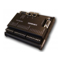
Installation
The installation steps in this document describe how to connect the CIO-MICRO or
CIO-MICRO-CC I/O module to an In-Sight Micro vision system.
If connecting an In-Sight 5000 series or In-Sight 7000 series vision system to the
CIO-MICRO or CIO-MICRO-CC I/O module, refer to the In-Sight
®
CIO-MICRO and
CIO-MICRO-CC I/O Modules Installation Manual, which is available on the In-Sight
Explorer DVD and available for download from the In-Sight support site:
http://www.cognex.com/Support/InSight.
Note:
l Cables are sold separately.
l If any of the standard components appear to be missing or damaged,
immediately contact your Cognex Authorized Service Provider (ASP) or
Cognex Technical Support.
Connect the Power Wires
CAUTION: Never connect the I/O module to a power source other than 24VDC.
Any other voltage creates a risk of fire or shock and can damage the hardware.
Do not connect the 24VDC power source to any terminals other than the 24VDC
+ and – power terminals.
1. Verifythat the 24VDC power supply being used is unplugged and not
receiving power.
2. Use a screwdriver to loosen the I/O module's power terminals(labeled
24VDC + and –).
7
 Loading...