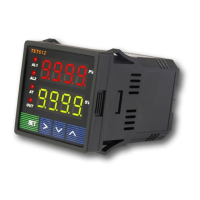
6. Connection Terminals (back view).
Polarity of power at terminal 1 and 2 do not matter. The “R” is not an external resistor; it is only
available from the Pt-100 thermistor.
Relay J1: #3, #4 = normally closed, #4, #5 = normally open
Relay J2: #13, #14 = normally open
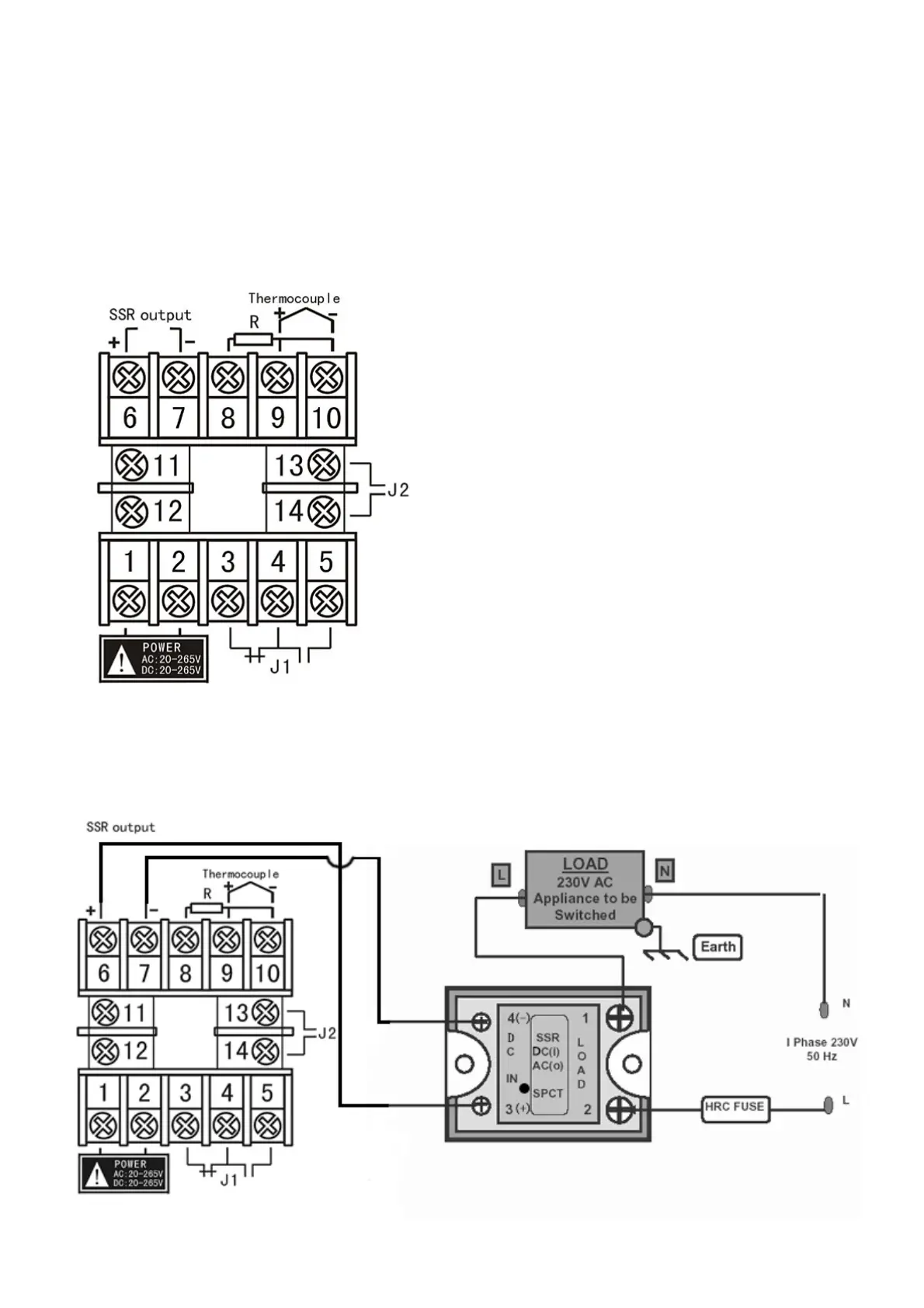
Fig 7
SSR Control
Caution: a heat-sink is required for the SSR
Relay J1 Control
Note: terminal #11 is an opened slot and
there is a diode installed for ambient
temperature referencing. It’s not a missing
screw or defective. For DC type controller,
the power is 12V ~ 32V. The ‘R’ is not a
resistor but it is a feedback resistance from
the PT-100 probe. Do not reverse + / -
when installing a thermocouple. If so, the
increment and decrement reading will be
opposite. For PT100 probe, red wire goes
to #8 while two blues wires go to #9,#10
Pt100 - Red lead terminal 8
Blue leads to terminals 9 and 10
 Loading...