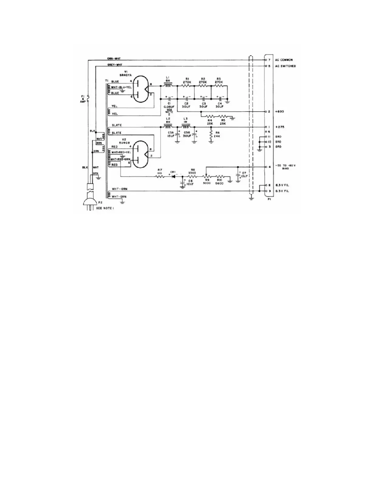
For reference, the schematic diagram of the un-altered 516F-2 power supply is shown below:
( ) Remove the yellow wire from pin #2 of V1 (5R4) and solder it to pin #5 of V1 (5R4).
( ) Remove the yellow wire from pin #8 of V1 (5R4) and solder it to pin #7 of V1 (5R4). These 2 steps isolate
the 5 VAC filament winding of the transformer as it is no longer needed.
( ) Remove the slate wire from pin #2 of V2 (5U4) and solder it to pin #5 of V2 (5U4).
( ) Remove the slate wire from pin #8 of V2 (5U4) and solder it to pin #7 of V2 (5U4). These 2 steps isolate
the 5 VAC filament winding of the transformer as it is no longer needed.
( ) Remove the blue wire from pin #2 on V2 (5U4) and solder it to pin #1 on V1 (5R4). Pin #1 of the 5R4 is not
used by the 5R4 or 516F-2. It will be used as a tie point for the dropping resistor.
( ) Mount the 200Ω 25-watt aluminum dropping resistor to a convenient location on the chassis. Connect and
solder one end of the 200Ω 25-W dropping resistor to pin #8 on V2 (5U4) and the other end to pin #1 on V1
(5R4) using the supplied #20 black wire.
( ) Connect the Metal Oxide Varistor (MOV) across the transformer primaries. Use one side of the fuse (ring
section, NOT tip) and rear tie point lug strip (the one with a green wire and white wire that connects to the
transformer primary windings. Note: This terminal is next to the ground terminal of the lug strip). The MOV
transient suppressor is the one that looks like a large ceramic disc capacitor. This will protect the
transformer primaries from line voltage surges.
( ) Replace the selenium bias rectifier, CR1, with the 1N5408 diode. Be sure to observe the correct polarity.
( ) Remove the old 5U4 and 5R4 tubes and replace them with the solid-state replacements.
( ) Assemble the meter protection diodes (2 x 1N4007 diodes back-to-back) according to the schematic
drawing below. This is most easily accomplished by placing the two diode bodies together (opposite
2
 Loading...