polarity) and wrapping the legs of one diode around the other, trimming and then soldering the wrapped
legs to the straight diode legs.
( ) Attach the meter protection diode assembly directly across the meter studs in the transceiver (KWM-2) or
transmitter (32S-1/3), whichever may be the case. This protects the meter from slamming against the pin
when first turned on. Leave any capacitor that may be connected across the meter studs.
( ) Check all of your wiring and make sure the modifications have been properly installed before applying
power. You may want to check the output voltages of the supply before re-installing in the outer cabinet.
( ) Replace the power supply chassis back in the outer cabinet and re-connect all cables and switch power on.
Adjust R-9 bias potentiometer (right rear of the supply) for proper static current on the 6146's
(approximately 40-50 mA).
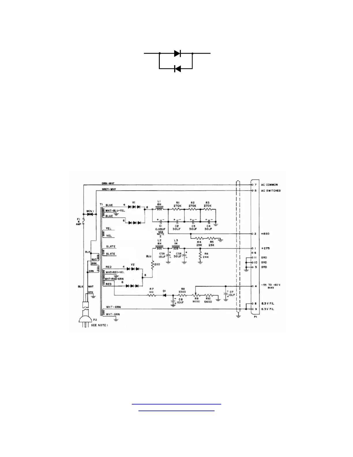
For reference, the schematic diagram of the solid-state 516F-2 power supply is shown below:
Special thanks to John May, K6MAY, for the use of this information.
HARBACH ELECTRONICS, LLC
Jeff Weinberg – W8CQ
468 County Road 620
Polk, OH 44866-9711
(419) 945-2359
http://www.harbachelectronics.com
info@harbachelectronics.com
3
 Loading...