Do you have a question about the Colorful A520M-K PRO V14 and is the answer not in the manual?
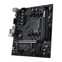
Supports Socket AM4 and 3rd Generation AMD Ryzen processors.
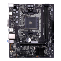
Based on AMD A520 chipset, supporting dual channel DDR4 memory.
Features 2 DIMM slots, dual channel DDR4, up to 64GB, 3200MHz+ support.
Includes PCIe 3.0 x16, PCIe 3.0 x1, and M.2 slot (SATA/PCIe 3.0 x4).
Provides 4*SATA3.0 ports for storage devices.
Offers 6*USB3.1 Gen1 and 6*USB2.0 ports (including headers).
Includes PS/2, USB, HDMI, VGA, LAN, and Audio ports for connectivity.
Features a 6-channel High Definition audio chipset with 3D sound.
Integrated 1000M LAN chipset supporting 10/100/1000Mb Ethernet.
Includes front panel headers, USB, FAN, COM, DEBUG, and SPDIF connectors.
Covers initial steps for motherboard preparation before installation.
Step-by-step guide for correct CPU and heatsink installation.
Procedure for installing DDR4 memory modules for dual channel.
Guide on securing the motherboard into the computer chassis.
Instructions for correctly installing the motherboard's I/O shield.
Steps for securing the motherboard with screws to prevent shorts.
Details for connecting power, internal headers, and setting switches.
Connecting 24-pin ATX and 8-pin PWR12V power supply connectors.
Function of JPS1 jumper for shutdown charging via PS2+USB.
Connecting SATA 3.0 6Gb/s hard drives and optical drives.
Connecting USB 2.0 module cables to the motherboard headers.
Header for connecting a speaker serial device.
Connecting chassis power/reset switches and LEDs.
Installing cards into PCIe x16 and x1 slots.
Connecting the chassis's front panel audio module.
Procedure for clearing CMOS settings using the jumper.
Installing M.2 SSDs into the motherboard's M.2 slot.
Connecting CPU, chassis, and power fan cables to headers.
Connecting RGB fans or LED strips to the 12V 4-pin header.
Connector for connecting USB 3.1 GEN1 devices.
Description and use of the motherboard's back panel I/O ports.
Procedure to enter BIOS setup using the DEL key.
Explanation of function keys for navigating and operating BIOS.
Overview of the BIOS main menu interface and options.
| Form Factor | Micro ATX |
|---|---|
| Socket | AM4 |
| Chipset | AMD A520 |
| Memory Slots | 2 x DIMM |
| Max Memory Capacity | 64 GB |
| PCIe Slots | 1 x PCIe 3.0 x16, 1 x PCIe 3.0 x1 |
| Video Outputs | 1 x HDMI, 1 x VGA |
| CPU Support | AMD Ryzen 3000/4000/5000 Series |
| Memory Support | DDR4 |
| Storage Interfaces | 4 x SATA 6Gb/s, 1 x M.2 |
| Audio | Realtek ALC662, 5.1-Channel |
| LAN | Realtek RTL8111H Gigabit LAN |
| Power Connector | 24-pin ATX power connector, 8-pin ATX 12V power connector |
| USB Ports | 4 x USB 3.2 Gen1 ports (2 on rear panel, 2 via header), 6 x USB 2.0 ports (4 on rear panel, 2 via header) |