Section 3
Emergency Procedures Columbia 400 (LC41-550FG)
RC050005 Initial Issue of Manual: December 9, 2005
3-14 Latest Revision Level/Date: C/10-10-2006
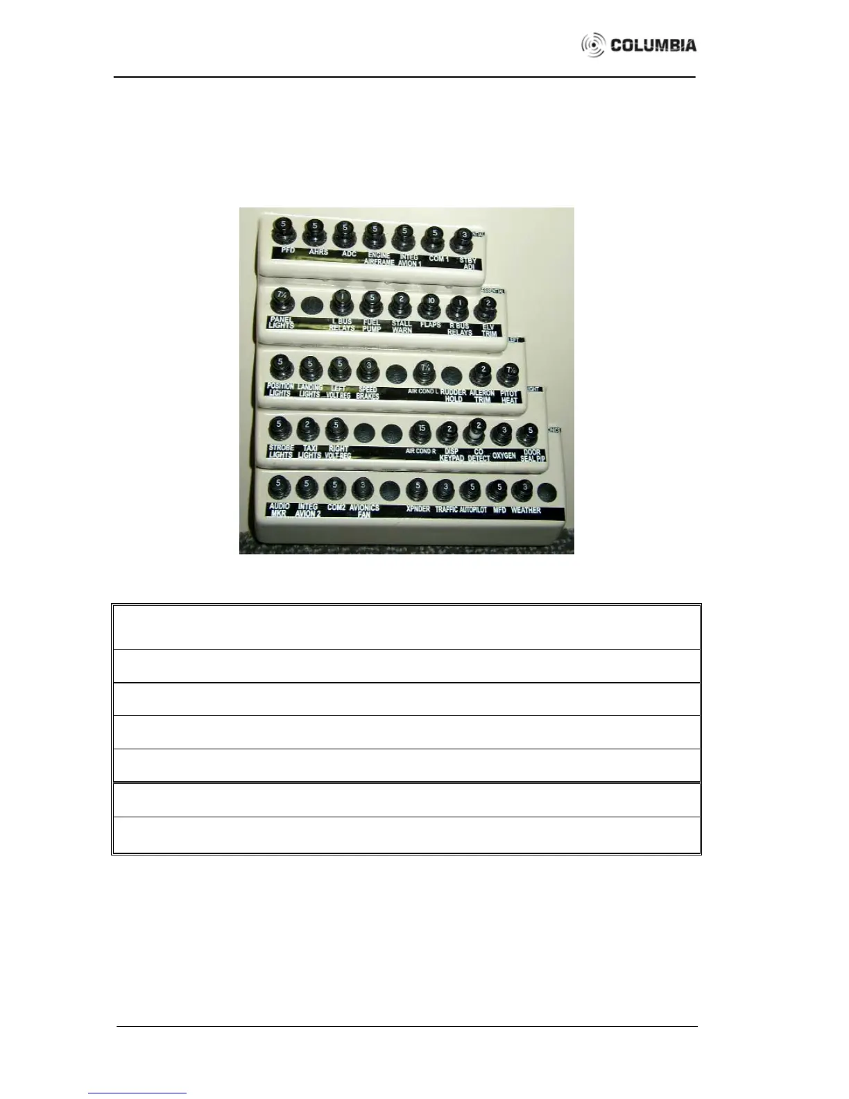
CIRCUIT BREAKER PANEL
Many of the above emergency procedures involve resetting or pulling circuit breakers, which
requires a good understanding of the panel’s location and layout. The circuit breaker panel is located
forward of the pilot’s front seat on the lower side-panel. A picture of the circuit breaker panel and a
table listing each circuit breaker is provided in Figure 3 - 2. See Figure 7 – 18 on page 7-42 for a
diagram of the electrical system.
Essential PFD AHRS ADC
Engine
Airframe
Integ
Avion 1
Com 1
Stby
ADI
Essential
Panel
Lights
●
L Bus
Relays
Fuel
Pump
Stall
Warn
Flaps
R Bus
Relays
Elv
Trim
Left Bus
Position
Lights
Landing
Lights
Left
Volt Reg
Speed
Brakes
●
Fan
Rudder
Hold
Aileron
Trim
Pitot
Heat
Right Bus
Strobe
Lights
Taxi
Lights
Right
Volt Reg
● ● ●
Disp
Keypad
CO
Detect
●
Door
Seal P/P
Avionics
Audio
Mkr
Integ
Avion 2
Com 2
Avionics
Fan
●
Xpnder Traffic Autopilot MFD Weather
●
Note 1: A ● indicates that the circuit breaker position is unused but reserved for future optional equipment.
Note 2: The actual arrangement may vary slightly depending on the optional equipment installed.
Figure 3 - 2
 Loading...